Continue to Site

Welcome to EDAboard.com

Welcome to our site! EDAboard.com is an international Electronics Discussion Forum focused on EDA software, circuits, schematics, books, theory, papers, asic, pld, 8051, DSP, Network, RF, Analog Design, PCB, Service Manuals... and a whole lot more! To participate you need to register. Registration is free. Click here to register now.

[SOLVED] ESR meter using 555 timer IC

Status
Not open for further replies.
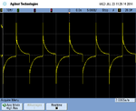
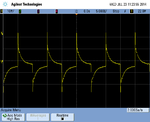
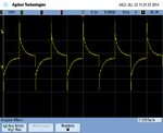
"When the output of the 555 goes low then the output of the 22nF capacitor goes well below ground (a negative voltage swing) which will reverse-bias the capacitor being tested."

I am simply challenging the statement that the electrolytic under test will get a noticeable, or detrimental negative pulse on it via the tester, in the following:

"Your 555 oscillator is feeding positive and negative AC to the capacitor being tested. Reverse polarity is bad for a polarized capacitor."

and via chuckey:
"So the capacitor under test has AC fed into it. i.e. its reverse biased every half cycle."
It is simply discharged each half cycle.
 

My very old oscilloscope is AC-coupled, not DC-coupled so I cannot view the circuit with the two capacitors in series.
 

Here's a scope capture of the circuit applying a 100 kHz square wave to a 1 uF electrolytic through a 22 nF. The capture is of the voltage across the 1 uF electrolytic. The scope is in DC mode and 100 mV/div and it can be seen that the voltage goes both positive and negative:

attachment.php


Here's a capture of the voltage across a 100 uF electrolytic; now the scope is set to 10 mV/div. The voltage is similarly symmetric about zero volts; it goes both positive and negative; there is no DC component to the voltage:

attachment.php


As long as the load on the output side of the 22 nF cap is linear with no non-linear elements like a diode, no DC voltage can appear there; capacitors don't pass DC.

- - - Updated - - -

To continue the discussion. I can connect a 1 megohm resistor in series with a 9 volt battery and momentarily connect that combination across the 100 uF capacitor. The 100 uF cap will slowly charge up and acquire a voltage which stays there for several minutes, slowly decaying through the scope probe back to zero volts of DC. Here the 100 uF cap has charged up a few millivolts in the negative direction:

attachment.php


Now I reverse the polarity of the battery and the 100 uF cap charges up in the negative direction, slowly discharging back to zero volts DC after several minutes:

attachment.php


In the absence of a diode or other non-linear component connected across the 100 uF cap, or the use of an external current source as I used here, there will be no DC component to the voltage across the cap. The cap will experience alternate, symmetrical, positive and negative excursions of voltage.
 

Attachments

  • scope_4.png
    scope_4.png
    26 KB · Views: 227
  • scope_3.png
    scope_3.png
    28.1 KB · Views: 200
  • scope_0.png
    scope_0.png
    27.9 KB · Views: 191
  • scope_1.png
    scope_1.png
    27.9 KB · Views: 187

As I said in my previous post the polarity across the capacitor is irrelevant to the operation of the circuit. The circuit is not very good, but the polarity across the capacitor is not one of my criticisms. No harm will come to the capacitor under test from this circuit.
 

I am just taking to task the irrelevant, inaccuracies, of: "the capacitor will experience a reverse voltage" and "the circuit is not very good."
 

Status
Not open for further replies.

Part and Inventory Search

Welcome to EDABoard.com

Sponsor

Back
Top