Continue to Site

Welcome to EDAboard.com

Welcome to our site! EDAboard.com is an international Electronics Discussion Forum focused on EDA software, circuits, schematics, books, theory, papers, asic, pld, 8051, DSP, Network, RF, Analog Design, PCB, Service Manuals... and a whole lot more! To participate you need to register. Registration is free. Click here to register now.

Ouput Conjugate Matching not done right?

Status
Not open for further replies.

Grecs

Newbie level 6
Joined
Jan 7, 2013
Messages
14
Helped
0
Reputation
0
Reaction score
0
Trophy points
1,281
Activity points
1,383
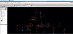
I have the schematic of the photo working at 2.4 GHz. I clearly get around 3V peak to peak before C0 but at my port2 (50ohm) I get like 160mV.

I have done matching and have checked it. Doing an SP simulation Z22 is approximately 50ohm with zero imaginary and Zm2 the same. Also S22 is around zero (10^(-3)) so I guess the matching is ok. Whats wrong with the power loss? I really cant understand and is buffling me some weeks....
 

Attachments

  • FC.jpg
    FC.jpg
    302.6 KB · Views: 96
Last edited:

You did DC short circuit the drain of M4 with M1 M0 switch circuit.( M0 and M1 act as a switch, not amplifier)
 

You did DC short circuit the drain of M4 with M1 M0 switch circuit.( M0 and M1 act as a switch, not amplifier)
hmm? Vsg=0.9V > |Vt|=0.5V
so Vsd>Vsg-|Vt|
Vs-Vd>0.9-0.5
1.8-Vd>0.4
so Vd<1,4V

To work on saturation. Isnt that right for the PMOS?

Also if I transient analyse the short circuit of drain of m4 with Source of m0-m1 I get 155mV peak to peak and at drain of M0 M1 I have 2.5V peak to peak.
 
Last edited:

hmm? Vsg=0.9V > |Vt|=0.5V
so Vsd>Vsg-|Vt|
Vs-Vd>0.9-0.5
1.8-Vd>0.4
so Vd<1,4V

To work on saturation. Isnt that right for the PMOS?

Also if I transient analyse the short circuit of drain of m4 with Source of m0-m1 I get 155mV peak to peak and at drain of M0 M1 I have 2.5V peak to peak.

Why don't you try to insert a ideal capacitor between 2 stages ?? I'm saying M4 does not amplify the signal properly because VDS voltage is very low because of short circuit (more or less)
 

I tried with capacitor before the node and the amplification is far worse and same problem occurs. Then I tried with inductor and results are the same. Loss of power after the L network. I read 2 papers with this topology and both use a short circuit between the D of nmos and S of PMOS. I think the problem is that I dont measure Zout properly.
 

I tried with capacitor before the node and the amplification is far worse and same problem occurs. Then I tried with inductor and results are the same. Loss of power after the L network. I read 2 papers with this topology and both use a short circuit between the D of nmos and S of PMOS. I think the problem is that I dont measure Zout properly.
Is the mid point connection of the coil connected to GND, is it midpoint ot substrate ??
If it's a midpoint, you made short circuit the supply.If it is not, check the DC operating point and post them here..
 

Status
Not open for further replies.

Similar threads

Part and Inventory Search

Welcome to EDABoard.com

Sponsor

Back
Top