Continue to Site

Welcome to EDAboard.com

Welcome to our site! EDAboard.com is an international Electronics Discussion Forum focused on EDA software, circuits, schematics, books, theory, papers, asic, pld, 8051, DSP, Network, RF, Analog Design, PCB, Service Manuals... and a whole lot more! To participate you need to register. Registration is free. Click here to register now.

VF circuit not functioning as expected?

Status
Not open for further replies.

steve_rb

Full Member level 3
Joined
Feb 17, 2004
Messages
184
Helped
1
Reputation
2
Reaction score
2
Trophy points
1,298
Activity points
1,538
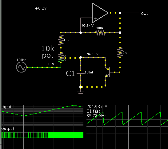
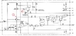
Attached circuit is a Voltage to frequency converter. Input is pin 5 (0-10 V) and out put is pin 9 (500HZ-40000HZ). When pin 5 is connected to the ground I have 500 HZ at the output. I tried to decrease this to below 200 HZ using R13 potentiometer but it has no effect on point "A" and so on the output at all. It only changes voltage at point "B" but no change at the voltage of point "A". That is why I couldn't decrease the output frequency below 500 HZ so far. I put a few days on this but couldn't do this. Any advice what am I missing here? Parts are checked and there is no problem with the parts.

I need a detailed explanation on how this circuit is working to be able to decrease the output to below 200 HZ for zero input.
 

Attachments

  • VF.JPG
    VF.JPG
    90 KB · Views: 59
Last edited:

No input, IC1 - is negative so O/P is +, when positive input is applied, IC1 O/P starts to go negative as C2 charges. At some O/P voltage will flip the gates, and cut off the current in Q2, so The input goes negative and C2 discharges as the output goes positive, the gates will flip again, taking you back to where you have started. So the speed of the circuit is set by the charging current into ICI -, part of which is the leakage down the Q2 path and part by the input voltage. The low volts set the low frequency (C2 takes a long time to charge), high volts , high charge current, C2 charges rapidly. For maximum stability the + input of IC1 should be connected to earth via the same resistance as is connected to the - input (10K). So you are looking for excessive leakage through the Q2 path and if the action of the flip flop is not enough to cut Q2 off completely.
If the Q output of IC4 is pulling A too low (another diode in series with CR4/5)?.
Frank
 
Thank you for the explanation . I still want to know why I don't see any voltage change at point "A" as I play with R13 potentiometer whereas I see changes at the pin 6 of the IC2? Is it the way this it should be or something is wrong here? These fine and coarse potentiometers are supposed to adjust output frequency in order to calibrate the circuit but there is no change at the output frequency.

When I connect the input to the ground I have about 500 HZ signal at the output. I tried to turn R13 potentiometer to decrease this frequency to below 200 HZ but I couldn't. These potentiometers don't affect the output frequency at all. I want to know why?

Steve
 

It follows the input voltage with a little difference but it does not change with the two "fine" and "coarse" potentiometers. Let say input is 5 V and we have 21KHZ at the output. I am expecting to exactly adjusting this 21KHZ to 20KHZ using these two potentiometers. Aren't that this potentiometers used for?

Steve

P.S. I just meausred point "A" voltage is 1.8 volts when I had 4 V in the input (pin 5).
 
Last edited:

Q2 is a constant current generator such that when Vin = 0, the current flowing through Q2 charges the cap and causes the circuit to oscillate at the low frequency. To increase the output resistance of Q2, they stuck Q1 in its emitter, theoreticaly this should raise the output impedance of Q2 to 10 M+, and to adjust the "zero" current the bias on Q1 is changes by the pots and the op-amp. As I said before the current going through Q2 is too high, it might be because its gone leaky or one of the DC bias resistors has changed (C7 gone low in value?). Thinking about the no change of voltage at A.... The pots change the CURRENT through the transistor, not the voltage across it.
Frank
 
Thanks for the great explanation. As I understand pots will change output of IC2 and from there the FET transistor current will change which is same as Q2 current except a little base to emitter current and that will increase or decrease the current going into the IC1 and from there discharging time of C1 will increase or decrease which means output frequency will change. Am I right?
If yes now I can check Q2 current and other parts and see where is the problem located.
What surprise me is all my three modules act the same way. Is this giving a clue where the problem might be? I know caps can age with time specially electrolyte ones but I don't know my caps are all aged or not because this is a 40 years old module.

Steve
 
Last edited:

I have really stuck here and need help. Could others please comment on this too?

Steve
 

Although is fine to feed an input of several volts to the V-to-F converter and have it respond correctly...

However it is questionable whether the same converter can be made to respond correctly down to 1/20 of a volt input. At that point we are liable to have problems with voltage thresholds and offsets.

I once looked into various V-to-F converters while I was building a homebrew amp-hour meter. I could not find one I could use. They were either not linear enough, or did not have a large enough range of operation, etc.

I ended up devising my own. It didn't need to be complicated. It was reasonably linear. And its range of operation was around 30:1.

The input signal charges a capacitor. A comparator (or op amp) detects when its charge reaches 0.2 V. The output turns on a transistor, to discharge the capacitor quickly.

Screenshot:


It can respond (produce a frequency) when input voltage is greater than 0.2 V. For inputs less than that, the circuit does not produce a frequency.
 
Status
Not open for further replies.

Part and Inventory Search

Welcome to EDABoard.com

Sponsor

Back
Top