Continue to Site

Welcome to EDAboard.com

Welcome to our site! EDAboard.com is an international Electronics Discussion Forum focused on EDA software, circuits, schematics, books, theory, papers, asic, pld, 8051, DSP, Network, RF, Analog Design, PCB, Service Manuals... and a whole lot more! To participate you need to register. Registration is free. Click here to register now.

Battery monitors with a system of my own designing

Status
Not open for further replies.

rajaram04

Advanced Member level 3
Joined
Jun 17, 2012
Messages
871
Helped
6
Reputation
12
Reaction score
5
Trophy points
1,298
Location
earth
Activity points
7,687
Hello everyone :)

Here as shown below may be i am doing a totally wrong thing but . . .
i am trying to design a simple but a typical design of battery monitor (B.M.) for 3 batteries of each 4 volts 1 mAH , which i connected further in series to get 12 volts out
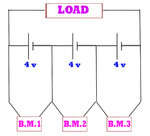
SAMPLE CKT 00.jpg

please tell me about errors & too explain about how to move it out

Reason i am designing it is just because when i connect any kind of full load for say 3 or 4 hours , i get a decrease in voiltage for each battery but with very diffrent value like

for battery near +ve side it shows 3 volts
for middle battery it shows 4 volts
& for last one near -ve side it shows 4.3 to 4.5

Given voltage regulation for batteries in standby mode are 4.7v-4.9v which i checked that all of them holds same value in rest

so i need a separate monitors for all of them ,
please help me in finding a right way
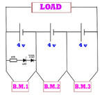
 

How about an led across each battery? One with a high forward voltage, say 3.5 V to 4V. While it's lit, the battery is good.

Probably some different color than red (red is typically less than 2V).
You can string together led's and diode's to add up to 3.5 V.

Add a safety resistor to limit current.

It is important that you do not let a battery fall to zero. Then it is in danger of being driven into reverse polarity by the other batteries.
 
A battery with a capacity of only 1mAh must be so small it is invisible.

What is the battery chemisty? Its voltage is too high for lithium. Maybe it is a 4.5V alkaline battery and you have three in series?
 
How about an led across each battery? One with a high forward voltage, say 3.5 V to 4V. While it's lit, the battery is good.

Probably some different color than red (red is typically less than 2V).
You can string together led's and diode's to add up to 3.5 V.

Add a safety resistor to limit current.

It is important that you do not let a battery fall to zero. Then it is in danger of being driven into reverse polarity by the other batteries.


oooo my god yesss the reverse polarity could be a great issue hmm..
well , idea for LEDs across each battery is preety cool & ofcourse a less complicated & less power consuming :)

a variation in the indication mode i am guessing is lighting behaviour of LEDs

In my monitor a single LED glow at a time indicating low charge , normal charge & over charge . .

& in case of single LEDs , low charge indicator LED (say RED) ll glow all the time.When battery enters charging mode the corresponding LED (say Green) ll glowup with low charge indicator LED & incase of over charge the corresponding LED (say blue) ll glow with all previous RED & GREEN LED & when we stop the charging ,blue one stops glowing but previous 2 LEDs ll glow continuously consuming power a lil.bit more than previous case

is it so ?

- - - Updated - - -

A battery with a capacity of only 1mAh must be so small it is invisible.

What is the battery chemisty? Its voltage is too high for lithium. Maybe it is a 4.5V alkaline battery and you have three in series?


mmm no sir its same a 4 volt sealed lead acid battery as we discussed earlier about all it & you explained many things . .
 

In this thread you said your battery has a capacity of only 1mAh. A tiny battery for a hearing aid has a capacity of more than 15mAh.
 
In this thread you said your battery has a capacity of only 1mAh. A tiny battery for a hearing aid has a capacity of more than 15mAh.


oooo so sorry its 1 Ah actually
as i ve my mind stuck with indicator issues so i got diverted there . .

well what you say ?
should i move for separate indicators as like in post #1 ?
or its a bad idea ?
should i go for only LEDs as per post #2 ?
 

I would do it this way:

lets call the negative end of the chain 'ground' for sake of discussion. Measure the voltages at the positive end of the cells and do this calculation:

Cell nearest ground voltage is measured directly at it's positive end.
The middle cell voltage is the measured voltage at it's positive end minus the previous reading.
The 'top' cell voltage is the measurement at it's positive end minus the voltage at the positive end of the middle cell.

This method gives you real voltages without resorting to circuits to monitor all three cells individually.

Brian.
 
Many people use an LM3914 bar graph IC and 10 LEDs (or less) to show the voltage of their lead-acid battery. You can setup the LM3914 so it lights only one LED called a Dot Display for low current.
 
ok we have many ideas here so now its turn to move for compactness all the way

- - - Updated - - -

Many people use an LM3914 bar graph IC and 10 LEDs (or less) to show the voltage of their lead-acid battery. You can setup the LM3914 so it lights only one LED called a Dot Display for low current.


ya sir i guess your idea is ok for a single battery of 12 volts or any . .
But after going through it i found that such level indicator graph ll show the total output from the combinational unit & not the level of an individual battery from the set

Here i am designing 3 indicator units & a single charger unit
which resembles
a function of petrol pump where a single pipe line is filling diffrent fuel tanks from diffrent vehicles & each of them have own fuel level indicators . .

I am doing it just because of diffrent readings from batteries after use
 

You need a LED across each battery and zener diode and small value resistor. This will allow the LED to go out when the voltage drops a small amount.
 
You need a LED across each battery and zener diode and small value resistor. This will allow the LED to go out when the voltage drops a small amount.

ok got it , so any proper biasing that circuitry needs actually ???

how to connect all the components with protection ?
 

Here is the circuit you need:
Add diodes until the LED starts to dim when the battery voltage decreases
 

Attachments

  • 3LEDs.gif
    3LEDs.gif
    189.8 KB · Views: 108
Last edited:
Here is the circuit you need:
Add diodes until the LED starts to dim when the battery voltage decreases


is the polarity o.k. about the signal diode ?
as we connect zener in reverse so . .
 

Hi,

monitoring is only half what you need. In my eyes a balancing unit is the way to get best overall performance.

My idea is to use a ucontroller with built in ADCs. With voltage deviders you can measure each cell voltage.
With two halfbridges you can manage to get equal voltage on every cell.

------
You should use three equal battery cells.
Different voltage come from different charge level in the cells (relative to total charge of the according cell)

Maybe because of ageing or tolerance one cell can store max. 1.2Ah, the other 1.0Ah and the next 0.8Ah.
Consider all cells are fully charged to this level.
If you now draw about 0.7Ah then the one is about fully discharged and showing a voltage level of 3.0V, where the other two still have about 4.0V.
If you further draw current, then the voltage of the weakest battery further drops and this cell gets damaged.

With a balancing circuit you keep voltages on all three batteries on the same voltage level.
The balancing unit then draws more current from the best battery and draws less current from the weakest battery.
With an optimal circuit you can draw 1.0Ah instead of 0.8Ah without the risk of damaging the weakest battery.

The same is when you cahrge the three cells in series.
Without a balancing unit the weakest battery sees the highest voltage and gets overcharged, again a risk of damage.

Klaus
 

Hi,

You cannot do this when the cells are in series because they all have the same current.

That´s exactely how the balancing unit with it´s two halfbridges work. The halfbridges generate additional - balancing - current (positive or negativ) individually to the cells.

Klaus
 

Status
Not open for further replies.

Part and Inventory Search

Welcome to EDABoard.com

Sponsor

Back
Top