Continue to Site

Welcome to EDAboard.com

Welcome to our site! EDAboard.com is an international Electronics Discussion Forum focused on EDA software, circuits, schematics, books, theory, papers, asic, pld, 8051, DSP, Network, RF, Analog Design, PCB, Service Manuals... and a whole lot more! To participate you need to register. Registration is free. Click here to register now.

[SOLVED] 30V 0.5A adjustable power supply with LM317

Status
Not open for further replies.

abuhafss

Full Member level 2
Joined
Aug 8, 2010
Messages
136
Helped
1
Reputation
2
Reaction score
0
Trophy points
1,296
Activity points
2,346
How to test regulator IC LM317?

Hi

I am building a power supply for my project based on LM317. I have failed with 4 different regulator ICs.

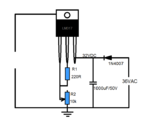
Here is the circuit which I assembled on breadboard.

Initially, I used 100 ohms for R1 and 5k POT for R2. When R2 has low resistance, I could get about 1.5V. But when I increase the resistance, the POT would start frying.......I could see the flashing inside the POT. At maximum resistance, the output was more than 30V.

Next, I used 220 ohms (didn't had 240 ohms) for R1 and 10k wire wound POT for R2. At low resistance of R2, I could get 1.5V but when I increase, this time R1 fried away instead of the POT.

I have checked 4 x LM317s and got same results. Input voltage is 32V 0.5A, and I haven't yet applied any load at the output except an analog 30V meter.

Does this means, all for ICs are faulty??? I have left the 5th one un-checked. Is there any other way to check if those regulator ICs are really dude?
 

Attachments

  • LM317.png
    LM317.png
    10.5 KB · Views: 116

Hi,
I do not know if I understand correctly. You should probably know that there will be losses in its circuit voltage, so the maximum output of the regulators has been 32v (Vout = 36v - circuit losses). If you want a maximum voltage of 30V at the output of your regulator u can by adding resistors or diodes to limit the voltage that u want.
This was help?
Hope this helps.;-)
 
Last edited:

I have also tested all 4 ICs with 24 volt input..............same results :sad:

R2=5k POT
At R2 minimum resistance -> 1.5V
slight increase R2 resistance -> 24V and R2 start heating up

R2=10K wire wound
At R2 minimum resistance -> 1.5V
slight increase R2 resistance -> 24V and R1 start heating up
 
Last edited:

I'm not really surprised.

36V AC will rectify to about 50V DC which is way beyond the limit for an LM317.

Brian.
 

I'm not really surprised.

36V AC will rectify to about 50V DC which is way beyond the limit for an LM317.

Brian.

I have checked the input, it is 32V not 50V!!
As mentioned in earlier post, I have also checked with 24V.
 

Add 1µF capacitor at the LM317 output.

- - - Updated - - -

But when I increase the resistance, the POT would start frying.......I could see the flashing inside the POT.

Something is wrong. The current from control pin 2 should only be a few µA.
 

Add 1µF capacitor at the LM317 output.

- - - Updated - - -

Something is wrong. The current from control pin 2 should only be a few µA.

The 1uF capacitor is not crucial for testing without any load of course, it is incorporated in the actual circuit.

Yes, the current from pin 2 should be 46-100 uA as shown in the datasheet.

I have tested the 5th regulator and got same results. Does this means all the 5 regulators are faulty? Is there any way to check LM317?
 

Yes, the current from pin 2 should be 46-100 uA as shown in the datasheet. (...) Is there any way to check LM317?

Have you measured the current in your setup?

- - - Updated - - -

I have checked the input, it is 32V not 50V!!

If you have 36V AC, the unloaded rectified voltage should be much higher than 32V, as betwixt has already mentioned. Why do you measure 32V? We would expect 50V which is more than the 40V maximum rating of the LM317.
 

I have not measured the current but, it is quite clear that it is large enough to heat up 0.25W carbon resistor.

I agree that the input voltage should be about 50V for a 36VAC but, in my case I am getting about 32VDC after half-wave rectification. Maybe something is wrong, which I'll check later.

For the time being, I switched to a 24V supply and replaced a fresh LM317 but still getting same results as shown in post no. 3 above.
 

This is RF & Microwave forum but anyway, I can bet the reason is the manufacturer of the regulator.
The market starts to be flooded with fake components, especially power MOSFETs, regulators and diode bridges.
 

This is RF & Microwave forum but anyway, I can bet the reason is the manufacturer of the regulator.
The market starts to be flooded with fake components, especially power MOSFETs, regulators and diode bridges.

Actually before posting, I have been searching older post to see for a similar post. One of the post was posted in this forum and I started new topic right from that point. I noticed, the forum later..............sorry.

Yes, I have also started thinking that all those regulators might be sub-standard quality.
 

Lm317 datasheet does not mention the maximum voltage..40V is differential voltage..dont use 36V transformer because differential voltage goes up to 50-1.5 (minimum output voltage ) = 48.5V...So only use 24V transformer..is lm317 heating up before the burning of resistors?
 

I have not measured the current but, it is quite clear that it is large enough to heat up 0.25W carbon resistor.

I agree that the input voltage should be about 50V for a 36VAC but, in my case I am getting about 32VDC after half-wave rectification. Maybe something is wrong, which I'll check later.

For the time being, I switched to a 24V supply and replaced a fresh LM317 but still getting same results as shown in post no. 3 above.

Because your're measuring rms value of half rectified sinusoidal wave.This is your fault because Multimeters measure rms value that is equivalent to DC.You shoud use a oscilloscope to meaure the peaks that burn your regulator.Filtering capacitor will be charged to the peaks but the rms value will be dropped due to discharging nevertheless peak values will stay same...
36VAC*1.41=50.7Vpeak !! LM317 can not resist to this voltage.
 

It's better to put big capacitors both at input and output of LDO.
Sometimes the both capacitors needs same value, otherwise the LDO can oscillate, for some LDO.
 

Yup, definitely your excessive input voltage is killing the reg chips

and much preferably, use a fullwave rectifier, a halfwave one is going to be pumping masses of ripple into the reg chip

Dave
 

Dude, tune that pot for maximum smoke!

Thanks everybody for their input.

The problem is solved with new LM317. It was really unfortunate for me to get all fake ICs which created a lot of frustration and wasted time.
 

Status
Not open for further replies.

Part and Inventory Search

Welcome to EDABoard.com

Sponsor

Back
Top