Continue to Site

Welcome to EDAboard.com

Welcome to our site! EDAboard.com is an international Electronics Discussion Forum focused on EDA software, circuits, schematics, books, theory, papers, asic, pld, 8051, DSP, Network, RF, Analog Design, PCB, Service Manuals... and a whole lot more! To participate you need to register. Registration is free. Click here to register now.

PIC16F877A not working even after bieng programmed successfully using ICD2(PICKIT2)

Status
Not open for further replies.

renuka gurmeet singh

Junior Member level 2
Joined
Jun 7, 2014
Messages
20
Helped
0
Reputation
0
Reaction score
0
Trophy points
1
Activity points
132
Hello Everyone...!

I have programmed my pic16f877a mcu using ICD2 programmer.And made a simple hardware of Led flashing.The hex file is successfully burned in IC,but its not working on hardware.Anyone help...
 

Is it plugged in? Are the pinouts correctly mapped? Is your software correct? Is your hardware correct? You give us no way of helping you.
 

What about the configuration words? How did u set it? Which osc r u using?
 

Show hardware and software... MCLR is connected to Vcc???
 

#include<htc.h>
#define _16F877
__CONFIG( HS & WDTDIS & PWRTDIS & BORDIS & LVPDIS & WRTEN & DEBUGDIS & UNPROTECT );
#define XTAL_FREQ 12MHZ
void delay(unsigned int);
void main()
{
TRISD=0x00;
while(1)
{
PORTD=0x00;
delay(300);
PORTD=0xff;
delay(300);
}
}
void delay(unsigned int ms)
{
while(ms>0)
{
ms--;
for(int j=0;j<220;j++);
}
}

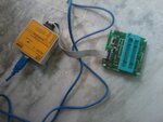
This is the code that i am using, its been successfully compiled in mplab.And successfully burnt by PICKIT2 (ICD2),I hereby attach the pics of programmar.Please help me to solve it,am getting totaaly confused,hardware connections are correct,software is correct then where's the problem :-( 2014-06-25 14.26.06.jpg

- - - Updated - - -

Show hardware and software... MCLR is connected to Vcc???

kindly check the ICd2 i have posted..
 

Hi,

It is difficult to see that board clearly, but it does look just like a programmer socket board.

As Nagkiller says you must have Pin1 Mlcre pulled up to +5v for the program to run.
If not fitted to the board you should be able to turn it on from MPlab or V 2.61 by the Programmer Menu option 'Turn Vdd On'

Also the 877A needs a crystal or similar to run , again cannot see any sign of that in that picture.

Can you post a schematic of the Flasher board so we can see exactly what it is ..
 

hello friend thanks to all for replying to my thread!!

I got the solution but dont know how it happens.In actual i was using a 12v transformer+rectifier and a regulator(7805) of 5v and regulator was producing a voltage of 4.2 volts,i think its sufficent for the pic16f877a to work but it was not working as per expectations.

So now i have changed the transformer to 24Volts and the MCU is geeting a supply of 5.6volts and its working fine.
But one question is bewildering me that the operating voltage of mcus is only 2.5 Volts then why its not worked on 4.2 volts.

Thanks friends problem got solved am happy. :-D
 

At 5.6V you will kill the PIC. You 5V or 4.7V. What was the current rating of 12V supply ?

- - - Updated - - -

What is the price of 877A at your place ? 2.5 USD ? Here for 3.5 USD I get PIC32MX250F128B (28 pin SPDIP). Its better to use PIC18F or PIC32 DIP package MCUs.
 

Stranger!!!

What is the function of the regulator? Regular!!!

12 or more is to be regulated 5V!!!

Check your hardware, it may be something wrong, a short solder between tracks, lack of GND, etc...

If you can show the electric scheme and perhaps also the pcb...
 

You gets 5.6v from 7805? it shouldn't go that high no matter how much input voltage used, it will dissipated all the excess power as heat. Try get another regulator and try again. Furthermore, from where you get the 2.5v mcu operating volt? 877a needs min 4volts to run and 4.2v you mention is on the lower end of the operating voltage range so try to stick to 5v...:wink:
 

Status
Not open for further replies.

Part and Inventory Search

Welcome to EDABoard.com

Sponsor

Back
Top