Continue to Site

Welcome to EDAboard.com

Welcome to our site! EDAboard.com is an international Electronics Discussion Forum focused on EDA software, circuits, schematics, books, theory, papers, asic, pld, 8051, DSP, Network, RF, Analog Design, PCB, Service Manuals... and a whole lot more! To participate you need to register. Registration is free. Click here to register now.

[SOLVED] 60 seconds timer reset problem using 74192 & 7447 decoder

Status
Not open for further replies.

corpuralx

Junior Member level 3
Joined
Oct 12, 2013
Messages
26
Helped
0
Reputation
0
Reaction score
0
Trophy points
1
Activity points
253
60 seconds timer reset problem using 74192 ic & 7447 decoder

I am building a digital clock timer using 74192 and 7447 decoder. Hertz is 1 (1 sec) clock. On proteus, on the tenth of seconds, i trapped the #2 and #4 bit which equals to 6 with AND gate then connected to reset of the 74192 so when it reached 60 secs, it will reset, but what happens was after 39 secs, which should be 40 secs, it resets instead back to 00. Whats the problem? I searched the web, googled it, i did the right connection but it doesn't work.

It's like the small delay to trap the 60 sec is very long that the AND gate will still read the 1 on #4 at 0101 (5), then reads the same time the 1 on #2 at 0110 (6) ???

Any ideas?

Thanks

- - - Updated - - -

Update: My last resort is to use ic 4017 to trap the 60 seconds, but is there still anyway without using it? just using the AND gate and some connections? thanks

- - - Updated - - -

Update1: When I also use 4017, though it did reset 60. But the ones at minute segment doesn't count up.. like after 00:00:60 it just went back to 00:00:00 instead of 00:01:00..
 
Last edited:
Difficut to confirm without seeing your schematic but I'm suspicious of bits #2 and #4 being set when the result reaches 6. The binary equivalent of BCD 6 is 0110 not 1010 which suggests it should be bits #1 and #2. What value are you loading into the counter inputs (if any)?

Brian.
 

Re: 60 seconds timer reset problem using 74192 & 7447 decoder

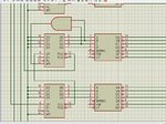
It's like this.

test1.jpg

So once it reaches 6 with high on #2 and #4 bit. It should reset. It does but too early. Instead of 60. it resets to 40. And also, it does not count up the "ones" in the next counter ic.. after 00:00:39 it just goes like 00:00:00 instead of 00:01:00 ...any idea?

- - - Updated - - -

All of my counter inputs (pin 15, 1, 10, 9) are connected to the ground.
 
Last edited:

Re: 60 seconds timer reset problem using 74192 & 7447 decoder

The AND gate sees two inputs changing at the same time. Depending on timing, a false pulse condition can occur. This is known as a race condition and to avoid the condition must be disabled during data transitions or sync'd with the same clock. "Ripple" counters are notorious for glitches unless you design a method to avoid the race condition.

Summary.
Unequal lag from 2 inputs changing into AND gate cause glitch reset.
Choose a better reset method with no glitch such as AND delayed by FF clocked on opposite edge, or 3 input GATE including inverse clock or brute force adding a 0.1 uF cap on MR to prove it is a glitch.
 
How about the 4017 ic method? It does reset on 60 but doesn't count up the "ONES" place on the next 74192 ic.? any ideas?

AND delayed by FF clocked on opposite edge, or 3 input GATE including inverse clock or brute force adding a 0.1 uF cap on MR to prove it is a glitch.

Im a little confused. Im still a newbie. Do you have schematic for this? Thanks
 

Corp.< your information of schematic and layout are too vague to see the whole picture.

4017 counter has 3 inputs; 2 for clock, 1 reset (MR).

Any output can be fed to MR to reduce /10 to /N, but MR pulse will be very short.
 

Edited. Please see below the image of the circuit i made.
 
Last edited:

here's ang image file, click to enlarge...

clk.jpg

any idea guys?
 

I tried nand gate then connecting it to the load, still the same. Tried the 2 diodes and resistor pull up, still the same. did the 4017 ic but the MIN won't count up.

I tried..

brute force adding a 0.1 uF cap on MR to prove it is a glitch.

, it went up to 59 then 00, but the "ONES" at minutes, the next counter won't count up. After 00:00:59, it just went back to 00:00:00, instead of 00:01:00.. similar to 4017 ic...
 

Sorry for my earlier confusion, when you said #2 and #4 bits you should have said pin numbers not bits.

Like SunnySkyguy, I suspect you have a race condition, it is quite common when you use long chains of counters because each one adds a small delay of it's own and the bits don't all change simultaneously like you would expect. While some bit have changed and others are delayed the count sequence gets out of step for a short time, not enough to notice but enough that logic gates can respond to it and do strange things.

Try this simple modification: add a 100 Ohm resistor in series with the MR pin of the counters. At the junction of the resistor and the MR pin, add a capacitor to ground. I would suggest starting with 100pF and if necessary increasing the value up to about 1nF. See if that fixes it and let us know.

Brian.
 
Hi Good Day

Thanks for stating the problems. Im now trying to fix the race glitch.

add a 100 Ohm resistor in series with the MR pin of the counters. At the junction of the resistor and the MR pin, add a capacitor to ground. I would suggest starting with 100pF and if necessary increasing the value up to about 1nF

I did your advice but is was still the same. Yours was it only counts up to 39 then after that it reset back to 00:00, without counting up on the ones of minute. I tried changing the cap to 1nf, still the same.

WHen I changed it to 1uf. It counts up til 59 however, the ones in minutes section does not still count up to 1. What did I miss?

And by the way, some may thought Im already doing the breadboard stuff but I didn't yet. I want the circuit fixed first on the proteus before bredboarding it. WOuld that be possible to be fix in proteus before breadboard? Or do breadboard first?Thanks
 
Last edited:

This is how I would do it. Instead of reseting the seconds/minutes to zero, I used Preload with inputs "0000". You cannot use TCU to step the next stage as it only generate a clock pulse when changed from 9->0. So I use the PSET from the NAND gate to step the minutes.

Unfortunately, the minutes will show digit '1' when the power is ON. But anyway you have to find a way to set the clock time so it is no big deal. I also added a "RESET" button in case you need to use it as a timer.
 

Attachments

  • CORPURALX CLOCK.GIF
    CORPURALX CLOCK.GIF
    244.4 KB · Views: 1,418
Re: 60 seconds timer reset problem using 74192 &amp;amp; 7447 decoder

You cannot use TCU to step the next stage as it only generate a clock pulse when changed from 9->0.

I did this but at first, it doesn't work, the ones minutes steps to 1 everytime it hits 40 seconds, so what I did, I applied the advice of SunnySkyguy and betwixtby putting pull down cap, ...and it works perfectly well. :)

If we're just neighbors I'll really brought you pizzas. haha

I'll leave this open, I might encounter some problems by the time I reach hours.

Thank you very much guys. I really apreciated your help. :) Thumbs up!

- - - Updated - - -

You have my rating each of you guys. :) I'll test the minutes and hours, I hope it works.

- - - Updated - - -

I was able to work the minutes and hours too. Thank you very much again guys. :)
 

To be honest it's a long time since I designed using TTL devices, it's so much easier with programmable devices these days. I have also never used, or had need to use, Proteus so I have no experience with it.

Generally though, you should never leave input pins of logic gates floating so I would do something with all those unconnected pins. As to the carry problem, if my memory serves me correctly, the carry to the next digit leaves the 74192 after the first clock after the count has reached 9 so in your circuit that could never happen. By resetting the counter when it reaches 6 it never reaches the carry condition. Try moving the input to the minutes counter so it connects to the output of the AND gate (or the MR pin after the RC delay) instead of the TCU pin.

Brian.
 

Status
Not open for further replies.

Part and Inventory Search

Welcome to EDABoard.com

Sponsor

Back
Top