Continue to Site

Welcome to EDAboard.com

Welcome to our site! EDAboard.com is an international Electronics Discussion Forum focused on EDA software, circuits, schematics, books, theory, papers, asic, pld, 8051, DSP, Network, RF, Analog Design, PCB, Service Manuals... and a whole lot more! To participate you need to register. Registration is free. Click here to register now.

scaling and shifting op amp voltages

Status
Not open for further replies.

jainx244

Newbie level 3
Joined
Jun 5, 2014
Messages
4
Helped
0
Reputation
0
Reaction score
0
Trophy points
1
Activity points
27
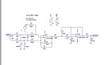
I have a differential input of +/- 10V from a sensor, which needs to be scaled and shifted to +/- 5V for driving ADC. I have been able to scale it to range +/- 2V. However, I am totally uncertain about the values of resistors and offset voltages that should be used. I am posting the image of my existing circuit. I have used sallen key topology for filter design. In my opinion I need a gain of 2 which I don't know how to do it with sallen key filter.

Any help would be highly appreciated.

Thanks,
 

Attachments

  • AnalogFrontEnd.jpg
    AnalogFrontEnd.jpg
    54.3 KB · Views: 136

You can adjust the gain by the value of 200k feedback resistor in the first opamp, e.g. to 400k or more. What are your Vcc and Vee?
The filter opamp is OK, the preamplifier offers the possibility of setting the gain.

- - - Updated - - -

The offset voltage if needed can be also adjusted by using a potentiometer across the voltage source as shown in your schematic.
 

Hi,

are R1 and R2 really 1000K = 1M??

Lower these values to get higher gain and lower noise, lower offset.
Use about 1k..10k, then adjust R8 for the gain you need.

Your max freq is about 1MHz?

Your input seems to be floating... this may be necessary, i don´t know.
If it is not necessary then try to pull the "+" input to GND. This ensures to be in a safe input common mode range.

With the simulation it may be no change, but in realitiy, especially with long wires to the sensor it makes a difference...

Hope this helps
Klaus
 

Hi Klaus,

Yes, R1 and R2 are 1M. Also, I have tried increasing the value of R8 to get the gain of 2 but it disturbs my frequency response. I have simulation running from 10Hz to 1MHz and sensor needs an output of +/-5V from 1KHz. Simulations at 1KHz is 0DB which is gain 1 and is highly unacceptable. I will go ahead and try with changing R1 and R2 value. There is a noise but could be ignored for the application. Safer the better.I am unsure of floating input at positive terminal. Could you give me more information. Thanks for the early response.

- - - Updated - - -

Vcc and Vee are 15V
You can adjust the gain by the value of 200k feedback resistor in the first opamp, e.g. to 400k or more. What are your Vcc and Vee?
The filter opamp is OK, the preamplifier offers the possibility of setting the gain.

- - - Updated - - -

The offset voltage if needed can be also adjusted by using a potentiometer across the voltage source as shown in your schematic.
 
Last edited by a moderator:

Hi,

.. floating...
Add a 1k resistor in parallel to c3.

Hope that helps
Klaus
 

I have tried setting the gain on the first stage which is not giving required frequency response at the output. I am looking for another alternative to solve this. I am not eager to add one more stage. Let me know if you have any other solutions.
Hi,

.. floating...
Add a 1k resistor in parallel to c3.

Hope that helps
Klaus
 

There is an EXCELLENT EXPLANATION by Thomas Fredericksen from National Semiconductor, on his book "Intuitive IC Op Amps from Basics to Useful Applications".
This book should be in everyone's library interested in op amps.

Let me see if I can scan the relevant pages. I've had problems with my scanner lately.
 

The criteria for component selection in your original circuit aren't particular understandable, neither are the simulation results (e.g. "0 dB at 1 kHz"). If the amplifier needs the MHz bandwidth indicated by the post filter, the differential amplifier resistors are definitely too high in value, both in terms of noise and parasitic time constants formed by circuit capacitance.

Instead of throwing together some arbitrarily selected components, you should start with a complete amplifier specification. If you need a high bandwidth + high input impedance differential amplifier, a true instrumentation amplifier or a similar circuit with high impedance differential input buffer would be definitely recommended. If the 1 MOhm impedance isn't essential, change the resistance level.
 

Status
Not open for further replies.

Similar threads

Part and Inventory Search

Welcome to EDABoard.com

Sponsor

Back
Top