Continue to Site

Welcome to EDAboard.com

Welcome to our site! EDAboard.com is an international Electronics Discussion Forum focused on EDA software, circuits, schematics, books, theory, papers, asic, pld, 8051, DSP, Network, RF, Analog Design, PCB, Service Manuals... and a whole lot more! To participate you need to register. Registration is free. Click here to register now.

[SOLVED] switching to charge pump circuit using transistor from main power to charge pump

Status
Not open for further replies.

sheng

Junior Member level 1
Joined
Jul 29, 2013
Messages
19
Helped
0
Reputation
0
Reaction score
0
Trophy points
1
Activity points
149
Hi,

My design circuit have a 6V (4AA) battery input and uses a LDO 3.3v. My circuit function up to 3.1V of the 6V battery. Instead of wasting the rest of the battery life, I have a low voltage detector in the circuit, once the battery reaches 3.1v, I want to switch to used the charge pump IC. My question is how do I design the circuit once it reaches 3.1v to use the charge pump Ic to run the circuit? The voltage detector is active low once the main battery is 3.1v. I am thinking of using transistor but don't know the right combo to make the switching. Thanks.
 

Hi KAM1787,
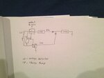
Thank you for replying, I read the two links but I am still a bit confuse on what to use for my situation. Please find attached picture below. I am trying to find a transistor or pair to replace the switch in the circuit. Any recommendation?

switchReplaceQ.JPG
 

Hi BradtheRad,

My idea was to use the 6v battery first until, it drain to 3.2v then I used the charge pump ic to supply the power 3.3v to the circuit. My circuit is limited at 3.1v this mean if I dont use a charge pump there is 3.1v wasted in the battery. So my idea is to run the fresh 6V down to 3.2v, then the charge pump ic work from 3.2v-1.6v to supply the 3.3v that is need for the circuit. The job of the voltage detector ic is to detector the 6v battery to 3.2v to signal the charge pump to wake up and generate the 3.3v. Thats why I need to break where the switch is in the picture with some transistor or ic. Any recommendation? Thanks
 

If you discharge the battery pack down to 3.2 V, then that means each cell is 0.8 V each. This is about the point where we call the cell discharged.

Furthermore there will be a voltage drop through all devices (diodes, transistors, etc.) which you install to switch the power source, boost the power source, etc. These will cause a burden on battery power.

Furthermore the cells may not discharge evenly. One cell could go down to 0V, with the other cells at 1V. Then the one cell will start to be forced into reverse voltage. This is likely to result in oozing electrolyte, and shortening of the battery's useful life.

As an alternate, consider a single buck-boost converter. This is a switched-coil converter which can step-down or step-up, by altering the duty cycle. It would step down your 6V to 3.3V efficiently, and it would step up your 1.6V to 3.3V efficiently.
 

Bradtherad is right, a buck-boost can undertake the task with a remarkably energy efficiency improvement. e.g. the LDO will at most give 55% while the buck-boost will easily give above 85% efficiency. The merit exists mainly in the heavy load conditions, and that's also when you need to notice the energy waste.

The buck-boost needs an external magnetic inductor which is with plastic package of certain height. This limit your application's miniaturization in 3D size.

In your innovation, without some feedback mechanism the CP output may have a large deviation from 3.3V, also the CP load may also load the LDO, doing harm to its stability unless you use an isolating power MOS or delicately arrange them. CP with feedback function is scarce to be found.
 

Thanks guys for the great feedback,
Do you guys have a recommend buck boost converter? Its my first time using one, I some read on google and came up with TI TPS61201. Would this be a good choice? Thanks
 

Hi sheng

TPS61201 is with the input voltage less than 5.5V, so recommend you to use only 3 series batteries.

Also please check your current rate compared to that of TPS61201, and consider to another choice if they are in very large scale.
 

Hi bill66656,

My current LDO is production 250mA output. The TPS61201 at 5V Vin seem to be production 1.2A and drop down as Vin decrease. 1.2A may affect my circuit.
 

TPS61201 is a boost converter, I recommend TPS61131/2, and it's with 300mA current capability, up to 90% efficiency, also fixed 3.3V output can save the ratio resistors out.

Please read its datasheet carefully!
 

Thanks bill66656, I will give TPS61131.
 

Status
Not open for further replies.

Similar threads

Part and Inventory Search

Welcome to EDABoard.com

Sponsor

Back
Top