Continue to Site

Welcome to EDAboard.com

Welcome to our site! EDAboard.com is an international Electronics Discussion Forum focused on EDA software, circuits, schematics, books, theory, papers, asic, pld, 8051, DSP, Network, RF, Analog Design, PCB, Service Manuals... and a whole lot more! To participate you need to register. Registration is free. Click here to register now.

Problem in Mosfet driving Using IR2110

Status
Not open for further replies.

nehe bhimaji

Newbie level 4
Joined
May 29, 2014
Messages
7
Helped
0
Reputation
0
Reaction score
0
Trophy points
1
Activity points
54
Dear All
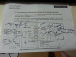
I am using Mosfet in Dual feed convertor mode for driving Inductor coil for Mechanical Vibration as given in AN of IR2110 . I Modified the connection and Ckt is attached here.The Circuit is driven by the PWM pulses from Arduino UNO with default PWM frequency 455Hz. As I start it Both Mosfets and IR2110 get Blast.I remove the Q1 Q2 D2 and R then it start working
Even though I have facing following problem


As i Increases the duty cycle of PWM for more Power then Mosfets and IR2110 gets Damaged. I have dought that My Bootstrap Capacitor is too small and there should be resistor between IR2110 HO LO and gate of the mosfet.
Please help if i am correct or Not
Thanks
 

Attachments

  • 20140525_113837.jpg
    20140525_113837.jpg
    1.9 MB · Views: 188

Dear All
Please help on my circuit
Thanks
 

Hi,

From signal side i think you need a pulldown resistor at HIN/LIN input to get true low voltage.

At the output side..
As far as i can see the circuit cannot output DC free AC, but i think this is needed for your solenoid. The solenoid usually gets very low ohmic when driven with DC. This may cause the high current that distroys your fet.

The rectifer is useless - at least i don 't understand it's meaning.
it is connected the other way round, as if one wants to generate AC out of an DC signal.

Klaus
 

Hii Klaus
Thanks For your reply.As i mentioned we require to drive inductor coil to generate the mechanical vibration for some production process.So we need to drive a inductor by these pwm. Rectifier is used to make 230 VAC to DC we need it .
We can not drive the coil using phase angle control by thyristor from AC input that will not solve our purpose.
Secondly i have tried to Pull down resistor at the input but without success.
Is there necessary to use separate 5 VDC to input for driving side of IR2110
Please suggest
 

Hi,

If you wnt the rctifier to make DC ot of AC, then it is connected the wrong way.

But i don't think you need it, because you get pulsed DC out.


For vibration you may need AC, then you need an H bridge. It is not clear to me what you really need...


Klaus
 

Hii Klaus
Yes Exactly I require Pulsed DC output.The vibration will control by changing duty cycle (Intensity of Vibration) and frequency of (Smoothness of Vibration) output.
I Put 1 k ohm resistor between Gate to source and 10 Ohm between HO and gate , LO and gate.Now Circuit is running for some say about one minute and all after Both Mosfets Gets Damaged.
Waiting for your reply
Thanks
 

Dear Klaus
Waiting for your reply
Thanks
 

Hi,

Are you sure the vibrating inductor works with pulsed DC?
To verify this you can measure the DC resistance of the inductor.

To debug your circuit it is helpful to place a shunt into the low side fet's source. Then connect a scope to see what happens.

My opinion...
Usually a vibrating inductor works with (pulsed) AC. This gives an alternating magnetic field. And the AC prevents the inductor from saturating. When saturating, the current increases while the vibration decreases.
If you see that the current is too high, then build a full bridge ( H bridge).
You can vary the vibrating frequency by changing the pulse frequency and you can change the vibrating intensity by varying the pulsewidth. Take care to mach the positive puslewidth with the negative pulsewidth to avoid saturation.
You may increase the pulsewidth with increasing frequency...
I'd try to control the H bridge in folowing sequence( Z = highZ, L = low, H = high)
Left half bridge - right half bridge
Z - Z ( both sides off)
L - H ( pulse forward )
Z - Z ( both sidef off)
H - L ( pulse backward)
... and so on
You can try ( L - L ) instead of ( Z - Z ). The first one is more to control vibrating force, the other is more to control vibrating amplitude.
It depends on your application what is the better solution...

Hope this helps.
Tell us more details...

Klaus.

Btw. I misinterpreted the use of the rectifier completely. Forget my comment on that...
 

Lets leave apart the the solenoid, motor etc. etc.
The problem is if the MOSFET is overloaded, only the MOSFET should blow, not the driver! Destruction of the driver insists something else...

1. I don't see any series gate resistor to limit the inrush sink/source current from the driver. 1R2110 can handle only 2A current. First and foremost, insert gate resistors.

2. Are you using electrolytic bootstrap capacitor? If yes, confirm polarity.

3. If you require DC pulses with variable duration, then a single switch is sufficient. Why make things so complicated? Confirm again whether you desire DC pulses or AC pulses.
 

Hi,

if the MOSFET is overloaded, only the MOSFET should blow, not the driver!

if fet blows and it accidentely connects between drain to gate then i see a chance to kill the driver...

I don't see any series gate resistor to limit the inrush sink/source current from the driver.
The schematic is from IR. They are very familiar with MOSFETs and driver circuit.
The fets usually can handle the short pulses of the driver and the other way round the driver can handle the currents.
I don´t see that there "must" be a resistor for current limiting.

But a resistor in the gate wire prevents from ringing. A value of 1 Ohm to 100 Ohm may improve this.
Take care: a series resistor increases switching time.
(For a halfbridge one needs extended deadtime between highside and lowside switching. )
With your circuit there is no danger of cross conducting, but expect higher switching loss.

Can you take a picture of your layout and show us?

Klaus
 

Are you sure a gate resistor is not required!! All the application notes that I have seen use a gate resistor. Without a Gate resistor, the pulse current may be as high as 10 to 15A!! And by the way the current limit of 2.5A for IR2110 is the pulse limit and not average limit, do you not agree?
 

Hi mrinalmani,

Are you sure..
I was not 100% sure, so i looked into the datasheet of IR2110.

In the table "Static Electrical Characteristics"
under "IO+" and there is the phrase "short circuit" and "VO = 0 V"... this says to me it is allowed to short the output to GND. The driver must survive this.
under "IO-" and there is the phrase "short circuit" and "VO = 15 V"... this says to me it is allowed to short the output to 15V. The driver must survive this.

current limit of 2.5A for IR2110 is the pulse limit and not average limit, do you not agree?
Yes, i agree with you.
I have allways seen the gate drive as a pulsed load, because the gate is very high ohmic. And after the FET turned ON or OFF there is about no current into the gate (100 nA with IRF830A).
So the average current from/to gate is quite low.

Now i look into IRF830A datasheet and find the total gate charge of 24nC. One nC = 1nAs.
With the given 455 Hz PWM frequency this means an average gate charge current of 24 nC * 455 1/s = 11uA.
The same is the gate discharge current.

The average current is very low.
In the highside driver all the gate charge current is supplied by the bootstrap capacitor of usually 100nF. There is not that much energy stored in it.

I just found the IR application note AN-978.
One sentence::
The value of the gate resistor should be as low as the layout allows, in terms of
overvoltage on the device and negative spikes on the VS pin.

I agree with you: it is better to design a gate resistor into the PCB layout. If not used one can put a 0 Ohms resistor in...

Klaus
 

I saw the datasheet again, actually you re correct. The driver pulse current is internally limited to 2.5A maximum. We do not require to limit it externally.
Actually I was comparing this IC with commonly available totem-pole BJTs.
In context of totem-pole BJT, maximum current means that the current should be limited to this limit externally. A typical example from a datasheet says.... Iav = 1A, Imax = 2.5A for t<10us.
However in context of IR2110, Imax 2.5A means that the maximum short circuit current is limited to 2.5A
 

Status
Not open for further replies.

Part and Inventory Search

Welcome to EDABoard.com

Sponsor

Back
Top