- Joined
- Jul 4, 2009
- Messages
- 16,232
- Helped
- 5,140
- Reputation
- 10,309
- Reaction score
- 5,120
- Trophy points
- 1,393
- Location
- Aberdyfi, West Wales, UK
- Activity points
- 137,370
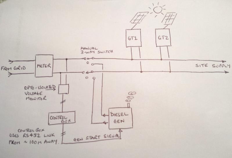
Scenario:
Power demand on a site varies between a minimum of about 200W, is typically around 500W and short term peaks (5 minutes at most) at about 10KW, the voltage is 240V and nominal frequency is 50Hz.
The site has three power sources, one from a power company, 4KW of PV from a grid tied inverter and a 6KW Diesel generator for back up.
Under normal operation, the PV assists the power arriving at the site by supplying some if not all of the demand, this is the good situation. Unfortunately, the incoming power is subject to frequent black outs and when that happens, the Diesel generator springs into action automatically to 'fill in the gap' until power is restored. However, the Diesel generator speed is not stable enough for the grid-tied inverters to maintain frequency sync so they automatically shut down, leaving a deficiency of 4KW in the supply. As a result, some machinery has to be shut down to keep the load within the generator's capacity.
A bigger generator is out of the question so a solution to stabilize it's output frequency is needed. The obvious answer is to convert the generator output to DC with a big rectifier, filter it and build a cystal controlled PWM sine wave output stage to convert it back to 50Hz again. Before looking into that possibility (reservoir caps on the DC being the biggest problem I foresee), can anyone see any other novel ways to achieve this?
Lateral thinking is needed - if it goes ahead the project will not commence for about 4 months so there is time to do a lot of planning.
Brian.