Continue to Site

Welcome to EDAboard.com

Welcome to our site! EDAboard.com is an international Electronics Discussion Forum focused on EDA software, circuits, schematics, books, theory, papers, asic, pld, 8051, DSP, Network, RF, Analog Design, PCB, Service Manuals... and a whole lot more! To participate you need to register. Registration is free. Click here to register now.

Is diode needed across current sense transformer primary of SMPS?

Status
Not open for further replies.
T

treez

Guest
Hello,
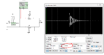
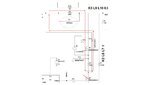
In the following current mode Two Transistor Forward converter, is the Diode (D1) absolutely necessary across the current sense transformer primary in order to prevent overvoltage of the top switching FET of the converter? As you can see, the overvoltage is due to ringing of the leakage inductance of the current sense transformer.

Also, do you agree that the freewheeling diode, (D13) must be connected to the input capacitor end of the current sense transformer primary, and not the other side of the current sense transformer primary?

(Schematic and LTspice simulation attached.)
 

Attachments

  • Current sense transformer.pdf
    19.8 KB · Views: 158
  • Current sense transformer.txt
    8.5 KB · Views: 99

single diode is not sufficient for over voltage protection , there must be resister and capacitor also connected after diode .
I think D1 is not required but D13 is necessary but study about snubber ckt before use it
 

1. I think the freewheeling diode is placed correctly. If it was placed without 'covering' the I-sense x-mer, then during the time the lower FET switches off, the the current would not flow through the x-mer.
2. The use of diode D1 is more to avoid the extreme voltage spikes due to opening of current carrying inductors, than to avoid ringing. Do you not agree?
 
  • Like
Reactions: treez

    T

    Points: 2
    Helpful Answer Positive Rating
1...sorry I don't understand, the decaying magnetising current is not really wanted to flow through the current sense transformer..surely...or is that what you were saying anyway?
2...Yes, I see your point, your exactly right, but the way it ends up is that the leakage inductance and the capacitance of the fet actually ring with a high peak voltage.

I am surprised that you agree with me though, as I have never seen a diode put like this across a current sense transformer primary
 

1.Yes surely it will ring but the amplitude of ringing is not something that can be overlooked. Consider the simulation attachment for a 250W transformer. The peak-peak voltage is around 4kV
2. Therefore the presence of D1 seems inevitable.
3. But placing D1 presents an immediate problem. With D1 connected, how will the I-sense transformer reset? It will simply saturate.
4. The solution seems to connect it such that it will reset "through the power transformer". And therefore the connection to the I-sense x-mer has been made the other way round. Do you not agree?
 

Attachments

  • Capture.PNG
    Capture.PNG
    61 KB · Views: 98
  • Like
Reactions: treez

    T

    Points: 2
    Helpful Answer Positive Rating
-the Current sense transformer (CST) cannot reset through the power transformer, as the power transformer is switched out by the fets when the CST needs to reset.
I don't believe the diode makes the CST saturate, because if it did, then the LTspice simulation would show the CST saturating. The LTspice simulation gives the expression for the magnetising current of the CST secondary, and if this is placed into the waveform window, you can then see that the magnetising current is not rising away into saturation.
So I do not believe that the diode makes the CST saturate.
(by the way, you can place the magnetising current expression into the waveform window by right clicking the waveform window, then going "ADD TRACE", then simply paste the expression given in the simulation into the dialog box}

The reset voltage required across the secondary of the CST in order to reset the CST is only about 9V. {remember that v.dt(on) must equal v.dt(off) for reset of the CST}.
If you refer 9V to the primary of the CST ,then its only 90mV. 90mV is not enough to forward bias the diode across the primary of the CST, so therefore the diode will be “invisible” to the reset pulse.
 
Last edited by a moderator:
1. Yes you are absolutely right. The diode will not saturate the x-mer. (I forgot about the high turn ratio)
2. But I don't understand why the I-sense cannot reset "through" the power x-mer. Consider the attachment below showing the path of current when the lower FET is OFF.
Perhaps the reason for an other way round connection may be this:

...First verify (from the attachment below) that the I-sense x-mer can reset through the power x-mer even when the lower FET is OFF...
Now, if the I-sense is allowed to reset "independently", it will reset extremely fast due to its small magnetization. Thus creating stress across the clamp components (in this case D1)
However if it it reset in series with the power x-mer primary, it will reset at a slower rate. This will reduce the spike across D1. Do you not agree?

- - - Updated - - -

And ofcourse the spikes have a handsome magnitude and best efforts should me made to keep them low
 

Attachments

  • Presentation1.jpg
    Presentation1.jpg
    65.8 KB · Views: 84
  • Like
Reactions: treez

    T

    Points: 2
    Helpful Answer Positive Rating
Sorry I do not understand, this is a 2 transistor forward converter and there cannot be conduction through the freewheel diode and the fet at the same time.
 

There is no need for a diode on the high current side of the CT, You can use a higher voltage diode than the 1N4148 on the signal side, then the reset volts on the CT can be very high (rather than clamped by the zener in your circuit) As it is a fwd converter there is plenty of time to reset the CT between power pulses, usually the capacitance of the winding on the CT limits the reset voltage and the rise time so that often a 100V diode (or a 1N4448) will suffice to do the job without being subject to overvolts during reset.
 
sorry, are you saying that the combination of the interwinding capacitance, and the alternate use of a higher voltage zener would mean that the diode was not needed on the high current side of the current transformer?

Sorry but I do not agree that interwinding capacitance is enough to do that. I am not sure what you mean about the 1N4148?, -are you saying you would get rid of the zener and just use a 1n4148 to do the reset?

If you run the simulation without the diode across the current transformer primary you can very clearly see why the diode is needed....there is no doubt, you would see the large overvoltages, and surely realise that the diode must be put across the primary of the CT?
 

Ah the simulation, does it have the winding C? if you try in the real world you might see a different result.

And no, they are two different and distinct things, diode not needed, and single diode on the CT signal side will work due to parasitics... usually.

(Also even if the 4148 or 4448 (better) breaks down in reverse on the CT the energy is low enough not to destroy the diode - i.e.it acts as a 75V zener, if the reset volts reach 75...)
 
Sorry but I just can't agree to letting the diode go into overvoltage breakdown in order to reset the transformer. Also, I am sorry but I cannot agree that adding in the interwinding capacitance would solve the overvoltage problem.....even in a current transformer, interwinding capacitance is not that much. -you can add interwinding capacitance into the simulation and it doesn't solve the problem of the overvoltage.

The diode on the primary side is surely needed, and as stated, this is due to the leakage inductance of the current sense transformer...surely you agree?
 

The diode across the CT - not needed, CT reset with just the diode - often done, V pk < Vmax of diode, due to capacitance of multi-turn winding

If you had built a converter similar to this, your experience would guide you....simulations often throw up things that don't really occur in real world due to real world parasitics...

Build and see...
 
  • Like
Reactions: treez and FvM

    FvM

    Points: 2
    Helpful Answer Positive Rating
    T

    Points: 2
    Helpful Answer Positive Rating
If the real world CT had the amount of leakage present in the simulation, then that kind of overvoltage would be seen in the real world. This is why the diode is needed across the primary. Interwinding capacitance isn't enough to stop that kind of overvoltage from that amount of leakage.
This is why the diode is needed. (the one across the primary)
In any case, even if the CT happened to have very low leakage, then having the diode there across the primary would do no harm.
So considering a batch of CT's....some of them may be poorly coupled, and for them the diode across the primary would be needed.
 

The diode across the CT does nothing in this circuit. If there is a spike on the mosfets, some snubbers or zeners across the mosfets would be a better approach...
 
its cheaper and easier to put a diode across the CT primary.
If you run the simulation with the CT with K=0.9, you can clearly see the spikes. Even of you add the capacitance to represent the interwinding capacitance, you do not get these spikes significantly reduced.

If your complaint about the simulation of the top post is that it does not have any interwinding capacitance... then you may easily add it in, and see for yourself that it makes no difference.
 

I appreciate the previous comment
Build and see...
And am curious to see real circuit results.

I think, there's nothing against providing a clamp diode option in the prototype PCB.
 
  • Like
Reactions: treez

    T

    Points: 2
    Helpful Answer Positive Rating
As you say, the diode across the CT primary certainly does no harm.
The time will be taken in winding a current transformer with K=0.9 or thereabouts.
I am pretty sure that you can tell that we are dealing with a simple concept here, "leakage inductance" in a current sense transformer, and the simulator does not get this type of thing wrong.

I suspect most engineers may never see such spikes as all of their current sense transformers are made with high coupling factors (and are relatively expensive off the shelf ones) ....but when you get CT's made cheap, then sometimes a number of them will be wound improperly, and you will see the poor coupling factor in those cases....you then need the diode across the CT primary.
As you know, it is easy enough to add in interwinding capacitance on the simulator, and if we do this, we will see that realistic values of interwinding capacitance cannot stop the overvoltages when the coupling factor between pri and sec of the CT is low.
 

I was talking about a diode option, the need should be however verified.

Regarding CT leakage inductance, for a roughly symmetrical toroid core winding it will be equal to the inductance of the air core transformer, in other words a piece of straigth wire. So it can compete with other circuit inductance contributions but won't exceed it by a large factor. If we imagine a high speed converter layout with multiple low inductance bus capacitors and sandwich power planes, the "wire" will probably matter, but the clamp diode as well.

If you worry so much about CT leakage inductance, why don't place it in series with the output transformer?
 
  • Like
Reactions: treez

    T

    Points: 2
    Helpful Answer Positive Rating
Basically the diode moves some of the ringing on the primary side over to the secondary side. But I wouldn't trust the simulator to handle interwinding capacitance realistically, since interwinding capacitance is not a simple lumped element.

Also you must make sure the presence of the clamp diode does not inhibit the resetting of the magnetizing flux each cycle.
 
  • Like
Reactions: treez

    T

    Points: 2
    Helpful Answer Positive Rating
Status
Not open for further replies.

Similar threads

Part and Inventory Search

Welcome to EDABoard.com

Sponsor

Back
Top