Continue to Site

Welcome to EDAboard.com

Welcome to our site! EDAboard.com is an international Electronics Discussion Forum focused on EDA software, circuits, schematics, books, theory, papers, asic, pld, 8051, DSP, Network, RF, Analog Design, PCB, Service Manuals... and a whole lot more! To participate you need to register. Registration is free. Click here to register now.

Fluctuation in ADC in PIC16F877

Status
Not open for further replies.

ecaits

Member level 4
Joined
Jan 16, 2014
Messages
76
Helped
0
Reputation
0
Reaction score
0
Trophy points
6
Activity points
579
Dear Sir,

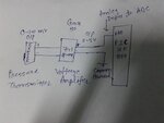
I have used ADC in PIC16F877 with hi-tech C compiler. I am measuring pressure in field through pressure transmitter giving 0-100mV. I am getting constant mV from pressure transmitter but when I am giving it to my controller, its fluctuate lots. My ADC resolution is 4.88 mV (analog input range 0-5V).

How can I solve my problem???

Nirav
 

Post the circuit.

Did you configured the micro-controller pin as analog?

You should not connect the sensor output directly to uC pin. Amplify the signal using op-amp.
 

hello,

No chance to get a good measurement with a so low full range signal..
ADC resolution +-4.88mV with ADC scale 5V => you will get +-5% of noise .
and 20 usefull points of measure instead of 1023 ..

Add an external rail to rail amplifier , like TLC271
or a programmable amplifier like MCP6S21
need a SSPI link 3 wires
Gain to initialise to 1,2,4,5,8,10,16,32

with 32 => 100x32=3200mV => 655 pts for full scale 100mV

Then you can apply an arithmetique filter or exponential filter to smooth /average the value.
 

Dear Paulfjujo,

This is say very nice solution. I want to implement it.
Can you suggest some circuit diagram using TLC271 or MCP6S21 amplifier which can give me exact output.

Thanks in advance...
 

Before you try anything else, try connecting a 0.1 uf capacitor between the adc pin and ground.
 

Analog filtering could not be the solution
Max analog input is 100mV, so
probleme is too poor ADC resolution .. or to small input range voltage for 10bit ADC 5V full scale..

With a TL271 you can fix the gain by yourself..
Maybe * 50 ( or 51,52) will give 100x50=5000 mV full scale
to correspond exactly with 10bits ADC scale input..
but you can get also, drift of zero volt ..by temperature change..
MCPS621 is more reliable .. but Gain=32 means less reolution
but same problem of zero drift (but less than TLC271).


At least, to avoid drift of zero volt with analog amplifier
a better solution could be an ADC adapted to this low voltage
and get with an Microchip ADC MCP 3421 combine a PGA +ADC
128mV full scale 2048 points resolution 62.5µV/point with Unit GAIN
up to ...128mV full scale 16384 points resolution is 7.8µV! with Gain=8

i tested versus MCP3424 (4 channel) successfuly with a maxima delta shift of 0.01% at 8µV/point
on short term and on a panel of 30 measures .

this comparaison table show relation chip with resolution
bute never compare Resolution and Accuracy
even there are close linked..

Comparatif_10_12_17bits.jpg
 

Can anyone recommend me standard voltage amplifier circuit??

Posted via Topify on Android
 

For optimum results, don't forget to set your conversion time and to really make sure you get a good clean conversion, put the core to sleep immediately after you start conversion and set it to wake up after the conversion is over. This will significantly reduce the noise levels within the PIC package.
 

Try this circuit.

105728d1400962155-prsense2adc.png
 

Attachments

  • prSense2ADC.png
    prSense2ADC.png
    20.3 KB · Views: 105

i think it can be solve by averaging. means take average of 5 last adc values and based on average it. you will get bit stable result. and for more stable increase the number to average.
 

I have used 741 op-amp as amplifier with 50 Gain so I am getting 0-5 V w.r.t. 0-100mV analog input. I have also used the averaging in ADC program. I have also tried 10uF capacitor connected to adc pin and ground. Still I am getting fluctuation in reading of ADC. What may be the reason for that???
 

I have used 741 op-amp as amplifier with 50 Gain so I am getting 0-5 V w.r.t. 0-100mV analog input. I have also used the averaging in ADC program. I have also tried 10uF capacitor connected to adc pin and ground. Still I am getting fluctuation in reading of ADC. What may be the reason for that???

Dear All,

Plz find schematic and code for reference.,

Nirav
 

Attachments

  • adc problem.txt
    4.7 KB · Views: 63
  • 20140528_170744.jpg
    20140528_170744.jpg
    1.4 MB · Views: 85

hello,

You problem is mainly in software ...

i tried your program with mikroC .. with litle changes to adapt the syntax
and it doesn't works well.. bad result on raw value get by the ADC
and i suspect also , a lack of memory wich can introduce some edges effects ...in my program :
very stange behavo=ior on my application on LCD , wich can not display the result..
because there is not so much RAM in this PIC.

you can simplify it like this
I suppress the table "int digital_out[20]" to save 40 bytes of RAM
not needed for averaging.. and use 32 average to use Right SHIFT instead of DIVIDE..
you can choose 16 .. but not 64..because oveload unsigned int.. or use long integer!
this one works fine and give a good raw result : example 32 values taken at 5V gives average= 1023 so,OK


Code:
  void ADC_Init()
{
   ADCON0 = 0x81;  // ADON = 1, Channel A.0 select, Fosc/32 select
   ADCON1 = 0x8E;    // 0x8E,0xC0 port a as analog, right justified output
}    //original 0x8E


unsigned int ADC_Read(unsigned char channel)
{
  int i; 
  unsigned int avg_output=0,temp=0, ;
  if(channel > 7) return 0; 

  ADCON0 &= 0xC7;        // AND= RAZ channel selection
  ADCON0 |= channel<<3; // OR = Set  chanel selection
  Delay_ms(3);
  for(i=0;i<32;i++)
        {   
            GO_bit = 1;
            _asm NOP  //  allways one instruction after setting bit GO
            while(GO_bit);  // Wait until conversion gets over
        Delay_ms(2);
            temp=temp+(unsigned int) (ADRESH<<8) + ADRESL ;   // Store 10-bit output into a 16-bit variable
        Delay_ms(5);
            
        }
Delay_ms(5);
//temp=32736;   // to test =32*1023
avg_output=temp>>5;    // use SHIFT to divide by 32 to avoid use of maths.h
return(avg_output);
}

with this code , no edges effect , and good result for displaying on LCD.

mikroC code for displaying the result :

Code:
char CRam[6];  // pour affichage integer maxi= 65536

// in main()
......
 M1= ADC_Read(0);
 Lcd_Cmd(_LCD_SECOND_ROW );
 WordToStr(M1,CRam0); // attention le buffer CRam0  ne doit pas etre trop long !!   sinon deborde du LCD...
 Lcd_Out_CP(CRam0);  
.......
 

Attachments

  • 8chVoltmeter.rar
    67.8 KB · Views: 59

Status
Not open for further replies.

Similar threads

Part and Inventory Search

Welcome to EDABoard.com

Sponsor

Back
Top