Rattanee
Newbie level 4
Hey guys, I'd like to ask for a little help regarding building a dual voltage powersupply.
A little background:
Since I have tons of arcade parts lying around, I decided to do something constructive and build a doorbell from some old pinball chime units I have using an AVR. I decided to use only components that I have as I don't want to shell out big bucks for a readymade powersupply or custom transformer for this project. Technically, the project needs approx 50VDC (this isn't a critical voltage, anything from 40 to 70 volts is okay really) for driving solenoids, and 5VDC for the drive electronics with a common ground. Now I've built a lot of single supply PSUs, but that is textbook stuff really. This dual supply has me confused to hell and back though.
The PSU:
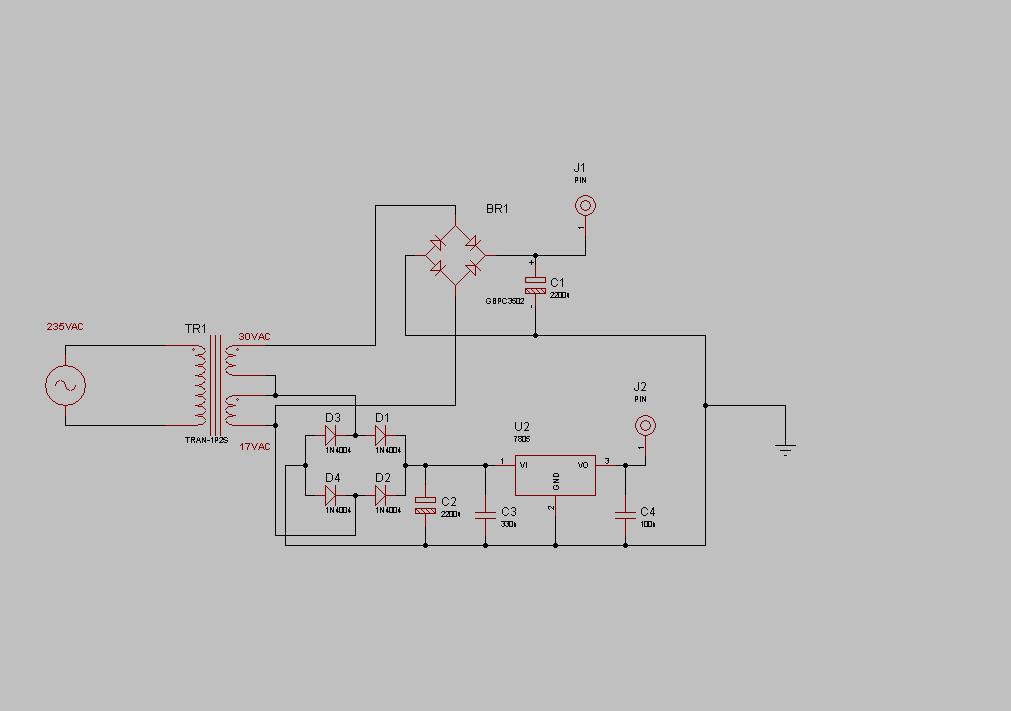
I found a transformer that has two secondaries, ~17VAC and ~30VAC. This seemed perfect for the task, as rectified 17VAC fed into a 7805 will work fine for the 5volt supply, and connecting the two taps in series, I can get ~47VAC which after rectification would be perfect for driving the solenoids.
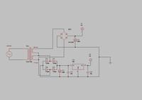
What I did was draw them up each as if they were separate powersupplies, and connected their negative leads for common ground. (See attached schematic) This however resulted in 55.9VDC at the input of the 7805, and 70VDC at the other PS output.
I attached a pic of my current circuit. What's wrong here? I'm probably missing something obvious, or doing something unorthodox with this design... Reading the AC inputs to the rectifiers, they're 17.8VAC and 47VAC respectively, which should be good, but no voltage after the bridges reads what I expected them to read...
Thanks for any help guys
A little background:
Since I have tons of arcade parts lying around, I decided to do something constructive and build a doorbell from some old pinball chime units I have using an AVR. I decided to use only components that I have as I don't want to shell out big bucks for a readymade powersupply or custom transformer for this project. Technically, the project needs approx 50VDC (this isn't a critical voltage, anything from 40 to 70 volts is okay really) for driving solenoids, and 5VDC for the drive electronics with a common ground. Now I've built a lot of single supply PSUs, but that is textbook stuff really. This dual supply has me confused to hell and back though.
The PSU:
I found a transformer that has two secondaries, ~17VAC and ~30VAC. This seemed perfect for the task, as rectified 17VAC fed into a 7805 will work fine for the 5volt supply, and connecting the two taps in series, I can get ~47VAC which after rectification would be perfect for driving the solenoids.
What I did was draw them up each as if they were separate powersupplies, and connected their negative leads for common ground. (See attached schematic) This however resulted in 55.9VDC at the input of the 7805, and 70VDC at the other PS output.
I attached a pic of my current circuit. What's wrong here? I'm probably missing something obvious, or doing something unorthodox with this design... Reading the AC inputs to the rectifiers, they're 17.8VAC and 47VAC respectively, which should be good, but no voltage after the bridges reads what I expected them to read...
Thanks for any help guys