Continue to Site

Welcome to EDAboard.com

Welcome to our site! EDAboard.com is an international Electronics Discussion Forum focused on EDA software, circuits, schematics, books, theory, papers, asic, pld, 8051, DSP, Network, RF, Analog Design, PCB, Service Manuals... and a whole lot more! To participate you need to register. Registration is free. Click here to register now.

Help with AM modulator

Status
Not open for further replies.

Paul Solberg

Newbie level 2
Joined
May 16, 2014
Messages
2
Helped
0
Reputation
0
Reaction score
0
Trophy points
1
Location
Yakima Washington
Activity points
13
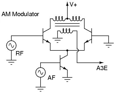
I designed and bread boarded this modulator:

Circuit.PNG

But the output is not nonlinear modulation, it's linear:

linear modulation.PNG

Does anyone know why it is not linear and what I need to do to fix it?

ammodulator1.PNG
 
Last edited by a moderator:

That circuit would appear to be the RF input stage, mixer, and IF stage of an AM receiver, not a modulator.
 

Its not a modulator?, there seems to be an aerial input then a mixer with an output at 455 KHZ selected, which is then amplified (twice) with an output to a detector (not shown). But your are right the waveform is of a high frequency with a low frequency super imposed.
Frank
 

The post is insonsistent regarding intended circuit function. It's also unclear how the waveform has been acquired.

I think, the mixer circuit can be also described as an AM modulator because part of the output signal is a product of both input signals, but only a small part.
 

.........................
I think, the mixer circuit can be also described as an AM modulator because part of the output signal is a product of both input signals, but only a small part.
It's true a mixer can be regarded as a modulator but that's not the usual use for the term. In radio work a mixer is used to convert one frequency to another using a multiplier circuit, typically as part of a receiver. A modulator is typically used to generate a transmitted carrier with an information signal added (modulated) on the carrier (also using some type of multiplier).
 

Circuit 2 is a more or less suitable AM modulator, with the disadvantage that the modulating signal is also appearing at the output. You need to extend the circuit to a double-balanced modulator to suppress the modulating signal.

I assume that the shown waveform has been acquired with circuit 2. But to see considerable modulation effect, the modulating signal must be higher, e.g. 1-2 V and the carrier lower, e.g. 10 mV.
 

A correction: To suppress the modulating signal output, you need a balanced output circuit, not a double balanced modulator. A double balanced modulator would be necessary to achieve a high modulation index (near 1) without distortion.
 

Status
Not open for further replies.

Part and Inventory Search

Welcome to EDABoard.com

Sponsor

Back
Top