Continue to Site

Welcome to EDAboard.com

Welcome to our site! EDAboard.com is an international Electronics Discussion Forum focused on EDA software, circuits, schematics, books, theory, papers, asic, pld, 8051, DSP, Network, RF, Analog Design, PCB, Service Manuals... and a whole lot more! To participate you need to register. Registration is free. Click here to register now.

[SOLVED] Complete understanding of "vsin" source in Cadence

Status
Not open for further replies.

jdp721

Member level 2
Joined
Jun 29, 2009
Messages
45
Helped
4
Reputation
8
Reaction score
3
Trophy points
1,288
Activity points
1,621
Hi.

I kind of thoroughly Googled before posting this question for seeking help from you guys! :wink:

The "vsin" source (in analogLib) of Cadence has many parameters:

i) AC magnitude, AC phase, DC voltage
ii) Offset voltage, Amplitude, Frequency,...


Question 1: Internet resources are indicating that parameters in (i) are for AC analysis, while that in (ii) are for Transient analysis - IS THIS TRUE? - because, I have seen in Cadence that changing the "AC phase" led to change in the Transient output waveform.

Question 2: what is the use of the "DC voltage" in (i) above? - because, I am seeing that people are setting this to '0 V' most of the times without any explanation!
 

Q1: Yes - it is for the AC analysis only. Are you really sure that the value of AC phase does influence the TRAN analysis? I don´t think so.
Q2: If you like, you can excite the circuit with an ac signal which is superimposed onto a dc level. However, in most cases, the dc operating point of the circuit is established using external bias voltages. In this case, set DC=0 in the ac specification.
 
Are you really sure that the value of AC phase does influence the TRAN analysis?

Yes, it does. With phase=90° you can start a sin wave with its peak value instead of its zero value in a transient analysis.
 
  • Like
Reactions: jdp721

    jdp721

    Points: 2
    Helpful Answer Positive Rating
Yes, it does. With phase=90° you can start a sin wave with its peak value instead of its zero value in a transient analysis.

I work with PSpice - and under Vsin there is a parameter called "phase" which, indeed, belongs to the TRAN analysis. Thus, Erik you are right!

But as can be seen here:
I have seen in Cadence that changing the "AC phase" led to change in the Transient output waveform.

the questioner speaks about a parameter called "AC phase". Typing error?

On the other hand, I agree that it makes no sense to use a phase specification for ac analysis.
 
the questioner speaks about a parameter called "AC phase". Typing error?

Hi, thanks for the replies :-D

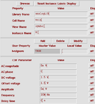
With regards to LvW's query, there is indeed an "AC phase" setting - attaching a screenshot taken from web to show this - changing this parameter changed the waveform found in Tran analysis!! - is it so that this field is common between AC and Tran analyses?

Vsin_cadence.png
 

the questioner speaks about a parameter called "AC phase". Typing error?

No, I don't think so. Other SPICE descendants (e.g. HSPICE, ELDO) and SPECTRE also use "AC phase" in this context.
Actually, it is the AC phase, isn't it?

On the other hand, I agree that it makes no sense to use a phase specification for ac analysis.

After all, there are reasons where you need it also for ac analysis: if you want to stimulate with two or more ac sources simultaneously, e.g. for differential inputs: View attachment AC_phase.pdf
 
To answer the original question, "what does the AC phase parameter" in VSIN schematic symbol, you should review the generated SPICE netlist. Both AC and SIN source have a phase parameter, but there seem to be only one phase entry in the symbol parameters. LTspice has e.g. an additional Phi parameter for the sine source.
 
  • Like
Reactions: jdp721

    jdp721

    Points: 2
    Helpful Answer Positive Rating
After all, there are reasons where you need it also for ac analysis: if you want to stimulate with two or more ac sources simultaneously, e.g. for differential inputs:

Yes - you are right, indeed it makes sense. Thank you.
 

Thanks to all for your kind replies :)

Let me conclude (using inputs from all sources) the outcome for help of future visitors:

Q1: Parameters AC magnitude and AC phase are only effective in an AC analysis. AC phase does not change the phase of vsin in a transient analysis. There is a parameter "Initial phase for sinusoid" than can be set to a non-zero value to set the phase of the source in a transient analysis.

Q2: DC voltage sets the DC value of vsin in a DC operating point analysis, or in AC analysis. This value can be different than parameter Offset voltage that sets the DC average of the vsin source in a transient analysis.

Bye!
 

Let me conclude ... the outcome for help of future visitors:

This is a very kind summary, Jdp, thank you,

... but those parameter selections differ for different SPICE program variants (e.g. there's no such selection "Initial phase for sinusoid" in SPECTRE).

So you should add for which SPICE program you found these conclusions.
 
  • Like
Reactions: FvM

    FvM

    Points: 2
    Helpful Answer Positive Rating
... but those parameter selections differ for different SPICE program variants (e.g. there's no such selection "Initial phase for sinusoid" in SPECTRE).

Yes, you are right. Initial phase, the last parameter of the SIN voltage and current source isn't present in the original Berkley SPICE which has only five parameters.
Code:
SIN(VO VA FREQ TD THETA)

The phase parameter has been later added in commercial versions.
 
  • Like
Reactions: erikl

    erikl

    Points: 2
    Helpful Answer Positive Rating
...e.g. there's no such selection "Initial phase for sinusoid" in SPECTRE).

So you should add for which SPICE program you found these conclusions.

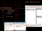
One question - maybe too trivial ;-) - Does the properties of instances from "analogLib" used in the schematic change with the simulator being used? In my case, to know which simulator I am using, I opened ADE, then Setup -> Simulator which showed that mine is "spectre"! (pls see the attached screenshot) - and the "vsin" had the "Initial phase for sinusoid" setting!

spectre simulator.png

Can you please shed some light on this.
 

Does the properties of instances from "analogLib" used in the schematic change with the simulator being used?

There are different views for different simulators. E.g. for SPECTRE a view named spectre is used.

... I opened ADE, then Setup -> Simulator which showed that mine is "spectre"! (pls see the attached screenshot) - and the "vsin" had the "Initial phase for sinusoid" setting!

View attachment 105290

Can you please shed some light on this.

I can see the parameter sinephase. Sounds different for me - even if the same is meant.
 

Status
Not open for further replies.

Part and Inventory Search

Welcome to EDABoard.com

Sponsor

Back
Top