Continue to Site

Welcome to EDAboard.com

Welcome to our site! EDAboard.com is an international Electronics Discussion Forum focused on EDA software, circuits, schematics, books, theory, papers, asic, pld, 8051, DSP, Network, RF, Analog Design, PCB, Service Manuals... and a whole lot more! To participate you need to register. Registration is free. Click here to register now.

Circuit to convert 6V DC to light a 220V, 14W CFL lamp

Status
Not open for further replies.

Albin George

Newbie level 4
Joined
May 4, 2014
Messages
6
Helped
0
Reputation
0
Reaction score
0
Trophy points
1
Activity points
56
i had an emergency lamp with a 6v, 4.5 AH lead acid battery & lighting a 14W, 220v CFL lamp, once i had dismantled it due to some charging problem. now i am trying to reassemble it, bt i accidentally cracked a wire from the board, and i am not getting from where it is came out (it is connected to a two way switch), so i need 2 assemble a new circuit i think.. can any body help me?? i need every details of making it, ('given i don't know anything about electronics, but i am good at soldering and all' :) )

i think my requirements are,

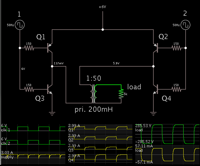
Convert 6V DC to AC current,
Amplify that AC to 220v (or 150 is enough i think) AC, i need no switches in the circuit.
also need to connect the battery charger to the same circuit,

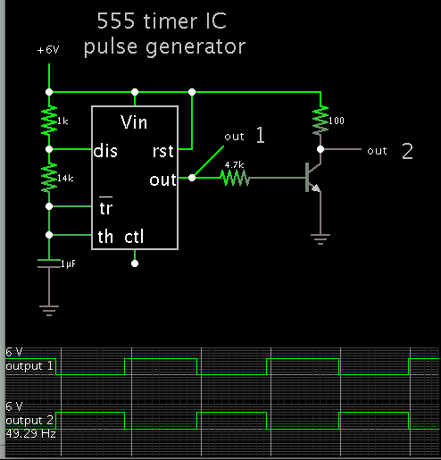
i also need a circuit for the charger, i have 240V 50Hz AC power outlet,

:!::!::!: please help..
 

If you "don't know anything about electronics" I would suggest you stay away from 220 volts. Far, far away.
 

If you "don't know anything about electronics" I would suggest you stay away from 220 volts. Far, far away.

thank u buddy for your reply and concern, but now i need to study electronics since i am planning my career with robotics also had several experiences with 220V ( i am a mechanical graduate, planing to seek more knowledge in the field of robotics but still newbie).. So please teach me yar, please.. 8-O
 

Someone may guess the connecting point if you post clear pictures of front and back of PCB,.
 

Someone may guess the connecting point if you post clear pictures of front and back of PCB,.

sorry, i think some other components in the pcb is also damaged, because while trying to re connect the wire i got several burns out of some points, after that none of the points on the board showed me any signs of voltage, so.... thanx for your reply buddy...
 

If the job is to turn 6 VDC into 220 VAC...
A convenient way to do it is by means of an H-bridge driving a step-up transformer.


Not shown is the driver circuitry. It will also need to be constructed.

The frequency does not necessarily have to be 50 Hz. It is a question as to what frequency the bulb needs to operate. There may be a suitable transformer on the circuit board. If so then it has an optimum frequency. It may not be easy for you to determine this.

About handling 230 VAC. I recall my first episode getting shocked unexpectedly by 230 VAC.
I was accustomed to 120V, but 230 V was worse. It hurt more, and left a burn mark on my finger where current entered my flesh.
 
tanks buddy for your help.. even though i hadn't understood your diagram well, i will work on it. :thinker: if you have time please explain in detail. what is driver circuitary?? my bulb need to operate at 50Hz. :-D:idea:

- - - Updated - - -

what does points 1&2 meant for?? and Q1, Q2, Q3 & Q4 ? i have a 500mh transformer, could that be used?

load is the point where we could add my cfl?
 

what does points 1&2 meant for?? and Q1, Q2, Q3 & Q4 ? i have a 500mh transformer, could that be used?

load is the point where we could add my cfl?

1 & 2 are clock signals, or pulse trains. These turn the transistors/mosfets on and off.

Q1-4 are customary transistor labels. The scope traces are labelled too.

It's possible your 500mH transformer can work, if it has the correct step-up ratio. Testing it will be tricky, because you must prevent high-voltage spikes. While testing, keep a load attached to the secondary when you send pulses into the primary.

You state your lamp is 14W, so it's wise to attach a 14W load. This would probably be in the form of a power resistor, about 5k ohms (as shown in my schematic).

My schematic is only a bare-bones configuration. I posted it to show you the basic concept. This project is bound to get more complex, and you can expect to burn up a few components as you run tests.

There's always the chance that it may not work in the end.

Barry's advice (post #2) is worth keeping in mind.

what is driver circuitary?? my bulb need to operate at 50Hz.

In this case driver circuitry means control circuitry. The two clock signals send bias current to the transistors.

An easy way to generate these pulses, using the popular 555 timer IC:


It can be powered by your 6V battery.
 

Status
Not open for further replies.

Similar threads

Part and Inventory Search

Welcome to EDABoard.com

Sponsor

Back
Top