Continue to Site

Welcome to EDAboard.com

Welcome to our site! EDAboard.com is an international Electronics Discussion Forum focused on EDA software, circuits, schematics, books, theory, papers, asic, pld, 8051, DSP, Network, RF, Analog Design, PCB, Service Manuals... and a whole lot more! To participate you need to register. Registration is free. Click here to register now.

400 V full wave diode bridge rectifier.

Status
Not open for further replies.

nalawade

Junior Member level 2
Joined
Apr 19, 2014
Messages
23
Helped
0
Reputation
0
Reaction score
0
Trophy points
1
Activity points
177
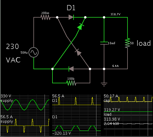
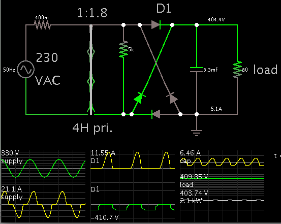
I want to make a full wave diode bridge rectifier whose output voltage should be Dc 400 volts.

I will be supplying it from the single phase 230 V 50 Hz Ac supply.

At the load side I will be connecting a Full bridge inverter circuit which will get dc supply of 400V from the diode rectifier.

The maximum output of the inverter should be 2kWatts.

Which diodes should I use?

How do I select the components for the diode rectifier circuit?

which transformer to use. what should be its ratings?

how to calculate the value of filter capacitor which will be between inverter and rectifier?
 

It's not clear how you will get 400 V from 230 V mains AC.
(Or is that is what the transformer is for? It will need to be 2 kW.)

This simulation shows how to get 318 VDC at 2 kW.


Although average current is 6.5A, it comes from the supply as large current pulses. How large they are depends on the overall input resistance. My simulation is only a guess.

The smoothing capacitor absorbs these pulses. It probably ought to consist of a bank of capacitors.
 

Thanks a ton :D

so 318 VDC is without the use of transformer?
 

You can use a PFC boost converter to raise the bus voltage to 400 V and improve the input power factor.
 

Thanks a ton :D

so 318 VDC is without the use of transformer?

It probably will not be higher. It probably will be less, because I would be surprised if the house current can provide jolts of 51A.

Figuring in terms of raw math...
The supply is 230 VAC nominal.
The peaks are 1.414 times that. So it's 325 VAC peak-to-peak.
Rectified and smoothed, it will be 325 VDC, with a light load.
Your load is heavy enough to pull it down several volts.

If you really want to get 400 VDC, then a step-up transformer is the conventional method.


You say you plan to attach an inverter.
Has anyone asked you, If you already have house current available to power your inverter, then why do you need an inverter? Why not use the transformer's stepped-up AC voltage?
 

I want to use inverter on the load side because I am making an induction cooktop. and for cooktop I need a high Frequency AC Voltage.

Can you tell me how do I calculate the value of the capacitor which I will use between Rectifier and Inverter ?
 

I want to use inverter on the load side because I am making an induction cooktop. and for cooktop I need a high Frequency AC Voltage.

Can you tell me how do I calculate the value of the capacitor which I will use between Rectifier and Inverter ?

Here is an example using 6.5A at 308 VDC (2 kW).
The load is equivalent to 47 ohms resistance.

A jolt of replenishing current arrives at the capacitor every 1/100 sec (50 Hz, full-wave rectified).

Suppose you permit 5% ripple. Then the volt level is allowed to fall 15V in 10 mSec.

Suppose you choose a smoothing capacitor 1000 uF (pulling a value out of the air).

Then the RC time constant is 47 mSec. (47 ohms x 1000 uF). Voltage would drop 63% in 47 mSec.

This is like a 13% drop in 10 mSec.

But you want only 5% drop.
Therefore choose 1000 uF x (13/5).
2600 uF.

As a check:

2600 uF x 47 ohms yields an RC time constant of .12 sec.
Voltage would drop 63% in that time.
Or, it would drop 5% in .01 sec. (Agreement.)

So 2600 uF will produce 5% ripple at 308 VDC, 6.5 A, 50 Hz.

As a comparison, notice the simulation (post #2) has a 10,000 uF capacitor, resulting in 1.7% ripple. (Calculated as the percent difference between 319.27 and 313.98).
 
If you do not use such a big reservoir capacitor, you save a lot of money and the peak currents around the circuits fall. The only downside is that the RF in the induction heater will be heavily modulated by the 100 HZ ripple. One way to explore, is that the output voltage falls to zero in the basic ripple, so if you have a second rectifier bridge being fed via a capacitor from the mains, this phase shifted AC would help to "fill in" the voltage between the ripple pulses. The diodes would also share some of the current.
Frank
 

Can you please tell me the significance of the 100 K resistor connected across the bottom diode ?


And also the 200m resistor in series with Vac . Is it the internal resistance of the supply ?

- - - Updated - - -

It's not clear how you will get 400 V from 230 V mains AC.
(Or is that is what the transformer is for? It will need to be 2 kW.)

This simulation shows how to get 318 VDC at 2 kW.


Although average current is 6.5A, it comes from the supply as large current pulses. How large they are depends on the overall input resistance. My simulation is only a guess.

The smoothing capacitor absorbs these pulses. It probably ought to consist of a bank of capacitors.


Can you please tell me the significance of the 100 K resistor connected across the bottom diode ?


And also the 200m resistor in series with Vac . Is it the internal resistance of the supply ?
 

Can you please tell me the significance of the 100 K resistor connected across the bottom diode ?

It is not needed in a real circuit. I added it because the simulation was pausing every cycle, as though it was having trouble reaching convergence.
Adding a resistor somewhere is a tactic that often gets you past a hangup.

And also the 200m resistor in series with Vac . Is it the internal resistance of the supply ?

Yes. The current spikes would be huge without it.

My simulation shows a 56 A burst lasting a millisecond, which may or may not be plausible. (I'm thinking about how an electrician will say a house has 60 amp service, or 100 amp, etc.)

It is informative to try different values for the supply resistance, and watch how it changes the waveforms.
 

Status
Not open for further replies.

Part and Inventory Search

Welcome to EDABoard.com

Sponsor

Back
Top