Continue to Site

Welcome to EDAboard.com

Welcome to our site! EDAboard.com is an international Electronics Discussion Forum focused on EDA software, circuits, schematics, books, theory, papers, asic, pld, 8051, DSP, Network, RF, Analog Design, PCB, Service Manuals... and a whole lot more! To participate you need to register. Registration is free. Click here to register now.

Generating pulses from a Triangle waveform

Status
Not open for further replies.

juz_ad

Full Member level 2
Joined
Dec 17, 2011
Messages
130
Helped
0
Reputation
0
Reaction score
0
Trophy points
1,296
Activity points
2,541
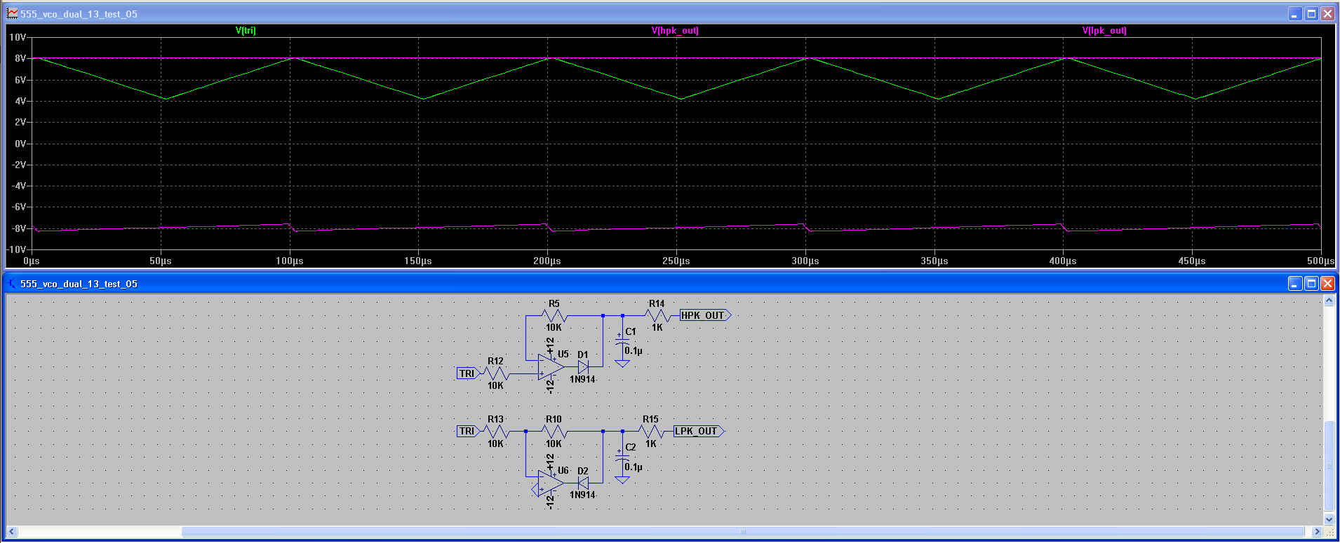
I have a requirement to generate two pulses of approx. μSec length from a triangle wave. One pulse is at the highest peak of the rising edge and the other pulse is at the lowest trough of the falling edge.

The triangle wave is fixed amplitude but varies in frequency between approx. 20Hz and 20KHz.

My current solution is manually setting two VRefs - one just below the peak and the other just above the trough which each triggers a comparator as shown below.

These pulses then trigger a SR Flip Flop that is High (or Low) on rising signals and Low (or High) on falling signals.

My concerns IRL is that any fluctuation in biasing or amplitude of the triangle waveform could put one Vref out of the voltage swing range of the VRefs and that with a manually set VRef there is a slight phase difference between triangle and pulse.

Can anyone suggest improvements or a better way to approach this.

Many thanks.
Screen Shot 2014-04-08 at 12.35.49.png
 

Depending on timing and accuracy constraints, one simple way to do this is using a peak detector-basically a resistor/diode/cap. The basic operation is as follows: using a voltage comparator, the non-inverting input gets the signal through an RC with a diode across the R, and the inverting input gets an attenuated version of the input signal. Thus, as the input is rising, the inverting input follows the input signal (minus the diode drop) and the non-inverting input has a lower voltage due to the divider. When the signal begins to fall, the cap will discharge slowly (through the resistor, since the diode is now reverse biased). When the signal falls far enough (depending on time constant and divider ratio), the non-inverting input will be higher than the inverting input, and the output will go high.

You can improve on this concept with more circuitry (to eliminate the effect of the diode drop, for instance) , but that's the basic theory of operation. This method does not require a threshold voltage; the trigger point is a percentage of the amplitude, rather than an absolute voltage level.
 

Thanks, that works well for the upper VRef but since my input waveform is not centred around 0V - is there a way to adapt this circuit to get a VRef for the 'lowest peak'?

My guessed adaptation obviously isn't cutting it!


Appreciated.
 

The suggested positive/negative peak detection method doesn't depend on absolute signal level if designed reasonably.

Alternatively, won't it be straightforward to differentiate the signal, getting a square wave and then detect the edges?
 

Since your frequency spans 3 decades, a differentiated square wave will span 3 decades in amplitude.

If the triangle wave is clean, then my favorite approach is an *analogic* frequency doubler.

** no such word, but seems appropriate.

saw2.jpg

Play with Java App > select Freq here (right click and edit generator value)

Exported Link

Note if signal is low use buffered inverter, if high, use unbuffered inverter, as each buffer stage has gain>10, 3 stage buffered inverter gain>1000 e.g. 'HC04
 
Last edited:

Status
Not open for further replies.

Part and Inventory Search

Welcome to EDABoard.com

Sponsor

Back
Top