Continue to Site

Welcome to EDAboard.com

Welcome to our site! EDAboard.com is an international Electronics Discussion Forum focused on EDA software, circuits, schematics, books, theory, papers, asic, pld, 8051, DSP, Network, RF, Analog Design, PCB, Service Manuals... and a whole lot more! To participate you need to register. Registration is free. Click here to register now.

[PIC] 18F4550 not working with external oscillator

Status
Not open for further replies.

iamnumber1chi

Newbie level 4
Joined
Mar 21, 2014
Messages
5
Helped
0
Reputation
0
Reaction score
0
Trophy points
1
Activity points
38
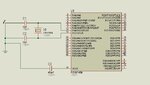
Just as the title states I'm trying to use my 18F4550 with an external 48 MHz crystal oscillator, but nothing I try seems to work. Though I can program the device, there appears to be no sign of the device running. It was working fine when I used the internal 8 MHz oscillator; only external oscillators are not working. I have read the datasheet and am using MPLAB X's built-in configuration bits tool to generate the configuration bits. Here is the program I have written:

Code:
#include <xc.h>

// #pragma config statements should precede project file includes.
// Use project enums instead of #define for ON and OFF.

// CONFIG1L
#pragma config PLLDIV = 12      // PLL Prescaler Selection bits (Divide by 12 (48 MHz oscillator input))
#pragma config CPUDIV = OSC1_PLL2// System Clock Postscaler Selection bits ([Primary Oscillator Src: /1][96 MHz PLL Src: /2])
#pragma config USBDIV = 1       // USB Clock Selection bit (used in Full-Speed USB mode only; UCFG:FSEN = 1) (USB clock source comes directly from the primary oscillator block with no postscale)

// CONFIG1H
#pragma config FOSC = HS        // Oscillator Selection bits (HS oscillator (HS))
#pragma config FCMEN = OFF      // Fail-Safe Clock Monitor Enable bit (Fail-Safe Clock Monitor disabled)
#pragma config IESO = OFF       // Internal/External Oscillator Switchover bit (Oscillator Switchover mode disabled)

// CONFIG2L
#pragma config PWRT = OFF       // Power-up Timer Enable bit (PWRT disabled)
#pragma config BOR = OFF        // Brown-out Reset Enable bits (Brown-out Reset disabled in hardware and software)
#pragma config BORV = 3         // Brown-out Reset Voltage bits (Minimum setting)
#pragma config VREGEN = ON      // USB Voltage Regulator Enable bit (USB voltage regulator enabled)

// CONFIG2H
#pragma config WDT = OFF        // Watchdog Timer Enable bit (WDT disabled (control is placed on the SWDTEN bit))
#pragma config WDTPS = 32768    // Watchdog Timer Postscale Select bits (1:32768)

// CONFIG3H
#pragma config CCP2MX = ON      // CCP2 MUX bit (CCP2 input/output is multiplexed with RC1)
#pragma config PBADEN = OFF     // PORTB A/D Enable bit (PORTB<4:0> pins are configured as digital I/O on Reset)
#pragma config LPT1OSC = OFF    // Low-Power Timer 1 Oscillator Enable bit (Timer1 configured for higher power operation)
#pragma config MCLRE = ON       // MCLR Pin Enable bit (MCLR pin enabled; RE3 input pin disabled)

// CONFIG4L
#pragma config STVREN = OFF     // Stack Full/Underflow Reset Enable bit (Stack full/underflow will not cause Reset)
#pragma config LVP = ON         // Single-Supply ICSP Enable bit (Single-Supply ICSP enabled)
#pragma config ICPRT = OFF      // Dedicated In-Circuit Debug/Programming Port (ICPORT) Enable bit (ICPORT disabled)
#pragma config XINST = OFF      // Extended Instruction Set Enable bit (Instruction set extension and Indexed Addressing mode disabled (Legacy mode))

// CONFIG5L
#pragma config CP0 = OFF        // Code Protection bit (Block 0 (000800-001FFFh) is not code-protected)
#pragma config CP1 = OFF        // Code Protection bit (Block 1 (002000-003FFFh) is not code-protected)
#pragma config CP2 = OFF        // Code Protection bit (Block 2 (004000-005FFFh) is not code-protected)
#pragma config CP3 = OFF        // Code Protection bit (Block 3 (006000-007FFFh) is not code-protected)

// CONFIG5H
#pragma config CPB = OFF        // Boot Block Code Protection bit (Boot block (000000-0007FFh) is not code-protected)
#pragma config CPD = OFF        // Data EEPROM Code Protection bit (Data EEPROM is not code-protected)

// CONFIG6L
#pragma config WRT0 = OFF       // Write Protection bit (Block 0 (000800-001FFFh) is not write-protected)
#pragma config WRT1 = OFF       // Write Protection bit (Block 1 (002000-003FFFh) is not write-protected)
#pragma config WRT2 = OFF       // Write Protection bit (Block 2 (004000-005FFFh) is not write-protected)
#pragma config WRT3 = OFF       // Write Protection bit (Block 3 (006000-007FFFh) is not write-protected)

// CONFIG6H
#pragma config WRTC = OFF       // Configuration Register Write Protection bit (Configuration registers (300000-3000FFh) are not write-protected)
#pragma config WRTB = OFF       // Boot Block Write Protection bit (Boot block (000000-0007FFh) is not write-protected)
#pragma config WRTD = OFF       // Data EEPROM Write Protection bit (Data EEPROM is not write-protected)

// CONFIG7L
#pragma config EBTR0 = OFF      // Table Read Protection bit (Block 0 (000800-001FFFh) is not protected from table reads executed in other blocks)
#pragma config EBTR1 = OFF      // Table Read Protection bit (Block 1 (002000-003FFFh) is not protected from table reads executed in other blocks)
#pragma config EBTR2 = OFF      // Table Read Protection bit (Block 2 (004000-005FFFh) is not protected from table reads executed in other blocks)
#pragma config EBTR3 = OFF      // Table Read Protection bit (Block 3 (006000-007FFFh) is not protected from table reads executed in other blocks)

// CONFIG7H
#pragma config EBTRB = OFF      // Boot Block Table Read Protection bit (Boot block (000000-0007FFh) is not protected from table reads executed in other blocks)

#define SYS_FREQ 48000000L

#include <stdio.h>
#include <stdlib.h>
#include <p18f4550.h>

int main(int argc, char** argv) {
    TRISD = 0x00;
    PORTD = 0x00;
    for(;;){
        PORTD = 0xff;
    }
    return (EXIT_SUCCESS);
}

Any help would be appreciated!

Cheers
 

For a 20 MHz crystal, the datasheet recommends 15 pf capacitors. So for a 48 MHz crystal I'm using 10 pf capacitors. I have tried a range of values for the capacitors but it doesn't seem to be where the problem lies.
 

Assuming that we are talking about a 2-pin crystal...

According to the datasheet, maximum crystal frequency for this PIC is 25MHz (or 24Mhz if using PLL)

48MHz 2-pin crystal is way out of specification.

External oscillator is not the same thing as crystal oscillator anyway. External oscillator is some source of square wave, such as 4-pin canned crystal oscillator for example.

Crystals do not produce square waves by themselves.
 
Thank you very much for pointing that out! What page of the datasheet was that on?

But perhaps I should add that I have also tried this with a 20 MHz ceramic oscillator and a 16 MHz 2-pin crystal but the problem persists. I thought the problem might have something to do with the configuration bits...
 

Thank you very much for pointing that out! What page of the datasheet was that on?
I have version E of the datasheet and the information is in table 28-8 parameter 1A
I thought the problem might have something to do with the configuration bits...
20MHz and 16MHz crystals or ceramic resonators require HS or HSPLL mode.
 
Hi,

Are you building on a breadboard ?

Have you tried using the internal oscillator to prove the chip and / or the program code are good ?
 

I have just checked and I can confirm the simple code working using the internal oscillator.

I've tried using my crystal with the HS mode as shown in the code I posted in the first post.

Is there something wrong with this device?
 

I have just checked and I can confirm the simple code working using the internal oscillator.

I've tried using my crystal with the HS mode as shown in the code I posted in the first post.

Is there something wrong with this device?
You are trying with a 16 MHz crystal now?
 
I have just checked and I can confirm the simple code working using the internal oscillator.

I've tried using my crystal with the HS mode as shown in the code I posted in the first post.

Is there something wrong with this device?

Hi,

You have not mentioned if you are using a breadboard ? - they can cause problems with such devices as crystals.
Whatever the method of construction the crystal and caps should be as close to the pics pins as possible.

Also what programmer are you using, notice you have Low Voltage Programming LVP=ON in your config
 
You have not mentioned if you are using a breadboard ? - they can cause problems with such devices as crystals.
Whatever the method of construction the crystal and caps should be as close to the pics pins as possible.

Thank you for your advice. Yes, I am using a breadboard and I have placed the 16 MHz crystal directly beside the OSC1/2 pins with two 22 pf capacitors going to ground. I still can't get an LED lit. Here is the code:

Code:
/* 
 * File:   18F4550_osctest.c
 * Author: Wyatt
 *
 * Created on 2014/03/22, 2:53
 */

#include <xc.h>

// #pragma config statements should precede project file includes.
// Use project enums instead of #define for ON and OFF.

// CONFIG1L
#pragma config PLLDIV = 1       // PLL Prescaler Selection bits (Divide by 5 (20 MHz oscillator input))
#pragma config CPUDIV = OSC1_PLL2// System Clock Postscaler Selection bits ([Primary Oscillator Src: /1][96 MHz PLL Src: /2])
#pragma config USBDIV = 1       // USB Clock Selection bit (used in Full-Speed USB mode only; UCFG:FSEN = 1) (USB clock source comes directly from the primary oscillator block with no postscale)

// CONFIG1H
#pragma config FOSC = HS        // Oscillator Selection bits (HS oscillator (HS))
#pragma config FCMEN = OFF      // Fail-Safe Clock Monitor Enable bit (Fail-Safe Clock Monitor disabled)
#pragma config IESO = OFF       // Internal/External Oscillator Switchover bit (Oscillator Switchover mode disabled)

// CONFIG2L
#pragma config PWRT = OFF       // Power-up Timer Enable bit (PWRT disabled)
#pragma config BOR = OFF        // Brown-out Reset Enable bits (Brown-out Reset disabled in hardware and software)
#pragma config BORV = 3         // Brown-out Reset Voltage bits (Minimum setting)
#pragma config VREGEN = OFF     // USB Voltage Regulator Enable bit (USB voltage regulator disabled)

// CONFIG2H
#pragma config WDT = OFF        // Watchdog Timer Enable bit (WDT disabled (control is placed on the SWDTEN bit))
#pragma config WDTPS = 32768    // Watchdog Timer Postscale Select bits (1:32768)

// CONFIG3H
#pragma config CCP2MX = ON      // CCP2 MUX bit (CCP2 input/output is multiplexed with RC1)
#pragma config PBADEN = OFF     // PORTB A/D Enable bit (PORTB<4:0> pins are configured as digital I/O on Reset)
#pragma config LPT1OSC = OFF    // Low-Power Timer 1 Oscillator Enable bit (Timer1 configured for higher power operation)
#pragma config MCLRE = ON       // MCLR Pin Enable bit (MCLR pin enabled; RE3 input pin disabled)

// CONFIG4L
#pragma config STVREN = OFF     // Stack Full/Underflow Reset Enable bit (Stack full/underflow will not cause Reset)
#pragma config LVP = ON         // Single-Supply ICSP Enable bit (Single-Supply ICSP enabled)
#pragma config ICPRT = OFF      // Dedicated In-Circuit Debug/Programming Port (ICPORT) Enable bit (ICPORT disabled)
#pragma config XINST = OFF      // Extended Instruction Set Enable bit (Instruction set extension and Indexed Addressing mode disabled (Legacy mode))

// CONFIG5L
#pragma config CP0 = OFF        // Code Protection bit (Block 0 (000800-001FFFh) is not code-protected)
#pragma config CP1 = OFF        // Code Protection bit (Block 1 (002000-003FFFh) is not code-protected)
#pragma config CP2 = OFF        // Code Protection bit (Block 2 (004000-005FFFh) is not code-protected)
#pragma config CP3 = OFF        // Code Protection bit (Block 3 (006000-007FFFh) is not code-protected)

// CONFIG5H
#pragma config CPB = OFF        // Boot Block Code Protection bit (Boot block (000000-0007FFh) is not code-protected)
#pragma config CPD = OFF        // Data EEPROM Code Protection bit (Data EEPROM is not code-protected)

// CONFIG6L
#pragma config WRT0 = OFF       // Write Protection bit (Block 0 (000800-001FFFh) is not write-protected)
#pragma config WRT1 = OFF       // Write Protection bit (Block 1 (002000-003FFFh) is not write-protected)
#pragma config WRT2 = OFF       // Write Protection bit (Block 2 (004000-005FFFh) is not write-protected)
#pragma config WRT3 = OFF       // Write Protection bit (Block 3 (006000-007FFFh) is not write-protected)

// CONFIG6H
#pragma config WRTC = OFF       // Configuration Register Write Protection bit (Configuration registers (300000-3000FFh) are not write-protected)
#pragma config WRTB = OFF       // Boot Block Write Protection bit (Boot block (000000-0007FFh) is not write-protected)
#pragma config WRTD = OFF       // Data EEPROM Write Protection bit (Data EEPROM is not write-protected)

// CONFIG7L
#pragma config EBTR0 = OFF      // Table Read Protection bit (Block 0 (000800-001FFFh) is not protected from table reads executed in other blocks)
#pragma config EBTR1 = OFF      // Table Read Protection bit (Block 1 (002000-003FFFh) is not protected from table reads executed in other blocks)
#pragma config EBTR2 = OFF      // Table Read Protection bit (Block 2 (004000-005FFFh) is not protected from table reads executed in other blocks)
#pragma config EBTR3 = OFF      // Table Read Protection bit (Block 3 (006000-007FFFh) is not protected from table reads executed in other blocks)

// CONFIG7H
#pragma config EBTRB = OFF      // Boot Block Table Read Protection bit (Boot block (000000-0007FFh) is not protected from table reads executed in other blocks)

#define SYS_FREQ 16000000L

#include <stdio.h>
#include <stdlib.h>
#include <p18f4550.h>

int main(int argc, char** argv) {
    TRISD = 0x00;
    PORTD = 0x00;
    for(;;){
        PORTD = 0xff;
    }
    return (EXIT_SUCCESS);
}

Also what programmer are you using, notice you have Low Voltage Programming LVP=ON in your config

I am using the PICkit 3. I take it this is a low voltage programmer?
 

Thank you for your advice. Yes, I am using a breadboard and I have placed the 16 MHz crystal directly beside the OSC1/2 pins with two 22 pf capacitors going to ground. I still can't get an LED lit. Here is the code:


I am using the PICkit 3. I take it this is a low voltage programmer?


Hi,

Only used the Pk2, but think the PK3 can be used as high or low voltage.
For LVP you normally have to pull the PGM /Rb5 low during programming, assume thats what the Pk3 pin 6 is used for.
There must be a check box in Mplab for selecting LVP somewhere..

If you are just using pins 1 -5 with nothing on pgm/RB5 then you want LVP=OFF so you program in high voltage on pin1 Mlcre.


Though many folk use breadboard with crystals, they are said to be good for only 1mhz.
Also the thin leads of the crystals and caps mean the connection is also poor.

Best thing to do is solder the crystal and caps together and solder on 3 thicker breadboard wire/pins to them so you have 3 thick pins to plug in to the breadboard.

Assume you are connecting the crystal to pins 13 and 14 ?


If that does not work, just worth adding a small cap around 470nf (not exact) to pin 18.
Believe (? )the use of config external crystal XT or HS invokes the usb function and it needs that cap (?)
 

Attachments

  • 000097.jpg
    000097.jpg
    34.8 KB · Views: 123
Status
Not open for further replies.

Similar threads

Part and Inventory Search

Welcome to EDABoard.com

Sponsor

Back
Top