Continue to Site

Welcome to EDAboard.com

Welcome to our site! EDAboard.com is an international Electronics Discussion Forum focused on EDA software, circuits, schematics, books, theory, papers, asic, pld, 8051, DSP, Network, RF, Analog Design, PCB, Service Manuals... and a whole lot more! To participate you need to register. Registration is free. Click here to register now.

Transistor to power IR LED using Rasberry Pi GPIO

Status
Not open for further replies.

Mark Baseggio

Junior Member level 2
Joined
Nov 2, 2013
Messages
22
Helped
0
Reputation
0
Reaction score
0
Trophy points
1
Activity points
249
Hey folks,

I'm designing an IR remote that can be controlled over the Internet using a Raspberry Pi and LIRC.

Since the Pi GPIO is 3.3v, and you're only supposed to source a max of around 18mA from each pin (or 50mA @ 3.3v total from all pins) I need to use something to give the TSAL7600 IR LED more power. Here is my circuit (note R1 is 220 ohms now not 47):
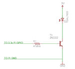
pi-ir.jpg

This design is "borrowed" from the TV-B-Gone (see the IR-Driver Transistors section), but the voltages are different. I want to make sure that I'm doing this right, so I don't blow up the Pi and also so I get the most power possible out of the IR LED. I'd like to turn this into a shield for the Pi at some point when I perfect the design.

I also put the design into Falstad's Java applet circuit simulator and realized I would have waaay to much current so I changed R1 to 220 ohms. See here: Simulated circuit

But I'm not satisfied that this takes everything into account and want to really learn more about what I need to consider when using transistors like this.

The LED is pretty beefy, datasheet for the TSAL7600 is here: https://www.mouser.com/catalog/specsheets/tsal7600.pdf

I'd appreciate your feedback! Thanks very much for your time.
 

A current limiting resistor in series with the LED is absolutely needed.
 

A current limiting resistor in series with the LED is absolutely needed.

I'm no expert, but I have read many opposing viewpoints on the matter. If you have a sec read the TV-B-Gone design notes page I posted up above, I trust the people that designed that thing and they didn't use one. My TV-B-Gone has been working for a couple years, totally fine.

Doesn't the resistor on the base limit the current flowing through the LED?
 

I'm no expert, but I have read many opposing viewpoints on the matter. If you have a sec read the TV-B-Gone design notes page I posted up above, I trust the people that designed that thing and they didn't use one. My TV-B-Gone has been working for a couple years, totally fine.
I suggest to review schematics of commercial products instead.

Doesn't the resistor on the base limit the current flowing through the LED?
It does, with a large uncertainty according to transistor current gain variations. And it maximizes transistor power dissipation.

In other words, it's the perfect solution if you think that a circuit shouldn't work by design but need individual adjustment to make your electronics hobby more exciting. :)
 

I suggest to review schematics of commercial products instead.


It does, with a large uncertainty according to transistor current gain variations. And it maximizes transistor power dissipation.

In other words, it's the perfect solution if you think that a circuit shouldn't work by design but need individual adjustment to make your electronics hobby more exciting. :)

What do you consider a commercial product? I bet you the TV-B-Gone has sold more units than many "commercial" products, it's commercially available at dozens of web sites. And the people that designed it are EEs that I believe know what they are talking about. At least, they seem to be highly regarded in the community. Anyway, not the point at all.

Edit: It's on Amazon, I think that makes it a commercial product https://www.amazon.com/Adafruit-TV-B-Gone-Kit/dp/B00F06LGNY/ref=sr_1_3?s=electronics&ie=UTF8&qid=1395239749&sr=1-3&keywords=tv-b-gone

Because I'm not an EE I still don't really understand the intricacies of the situation. Sorry for being dumb, but I'm scratching my head a bit on your second comment, I'm not sure what you mean.

It seems to me that because the LED is capable of dissipating all of that current, and due to the fact that the Hfe is certainly less than 100... the transistor will not be dissipating much current at all. Or is there a problem with my assumptions here?

Thanks again.
 

I do not know if the duration of the pulses to the transistor are shorter than the 100us on the datasheet of the IR LED.
I do not know if a very low ESR capacitor is in the power supply for the circuit because its little battery certainly cannot provide over 1.5A.

That IS a very powerful LED.
 

I do not know if the duration of the pulses to the transistor are shorter than the 100us on the datasheet of the IR LED.
I do not know if a very low ESR capacitor is in the power supply for the circuit because its little battery certainly cannot provide over 1.5A.

That IS a very powerful LED.

I'm using a 5v 2A power source for the LED, a wall-wart. Should put a capacitor somewhere near the LEDs? Eventually I will use 3xAA to power this, which should be able to provide more than enough current (it seems that they are capable of well over 2A). So, I guess I wouldn't need a capacitor in that case?

I've got a crappy mini dso and I am playing right now, I'm pretty sure pulses are shorter than 100us.
 

In fact there are many uncertainties involved with the circuit.

I see that the datasheet has a specification for forward voltage with 1A/100 µs pulses, 1.5 A is a surge specification in maximum ratings. (A surge specification would be normally read as "better avoid it"). According to data, it's a typical remote command IR LED, 90 % of any brand RC will use similar devices.

Current gain of 2N2222 at 1A isn't specified at all. The simulation results don't necessarily represent the real behaviour. I believe that the 2N2222 current gain characteristic will act as a natural current limiter over a wider range of base currents. As long as you don't set the pulse output to longer on-times by accident, there won't be a problem. Good design practice is a different thing, though.

A trivial motivation for a LED series resistor might be that it allows to measure the pulse current easily.

I remember that a typical RC circuit uses a storage capacitor for the LED driver with a resistor limiting the average current. The circuit would also protect the LED in case of inadvertent long pulses.

Yah, I'm struggling to measure the actual currents as I don't have the equipment. I have a Mini-DSO and a digital multi-meter, but with pulses so short I don't know how I can figure out what the real world values are here. Any ideas?

Thanks again for the advice!
 

A series resistor of e.g. 1 ohm between 5V and LED anode should allow a fairly correct measurement, presumed your mini-DSO can record at e.g. 50 or 100 µs/division.
 

Status
Not open for further replies.

Similar threads

Part and Inventory Search

Welcome to EDABoard.com

Sponsor

Back
Top