Continue to Site

Welcome to EDAboard.com

Welcome to our site! EDAboard.com is an international Electronics Discussion Forum focused on EDA software, circuits, schematics, books, theory, papers, asic, pld, 8051, DSP, Network, RF, Analog Design, PCB, Service Manuals... and a whole lot more! To participate you need to register. Registration is free. Click here to register now.

LM555CN output goes high during circuit power up

Status
Not open for further replies.

vikash23

Full Member level 2
Joined
Jul 31, 2012
Messages
133
Helped
3
Reputation
6
Reaction score
3
Trophy points
1,298
Activity points
2,676
Hi,

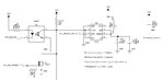
My LM555 IC toggles the output high during power up when the output time period is for greater than 5 seconds. When it is less than 5 seconds time period the output is low during circuit power up.

Below is circuit diagram and graph during power up condition. Please do help .

Thank you.


Oscilloscope graph during circuit power up.
LeCroy.jpg
 

Attachments

  • untitled.JPG
    untitled.JPG
    48.8 KB · Views: 82
Last edited:

Why is the supply voltage only 3.3V? The minimum allowed supply for an LM555 is 4.5V. Use an LMC555 for such a low supply voltage.

Why is the reset pin connected to the trigger pin?
 
Hi,

Sorry, In my PCB i reworked and connected the reset pin to VCC.

And my circuit works fine with 3.3V when triggered. So do you think the power up triggering problem arises because of my 3,3V ?

- - - Updated - - -

I also connected a 220nF capacitor from trigger pin(2) to ground.
 

Try using your LM555 with a 5V supply or replace it with a Cmos LMC555. The Cmos 555 has reduced output current.
 

I don't actually understand how different behaviour would be created by varying the timer time constant. Do you?

How about holding Reset low during power-up by an RC circuit?
 

"I also connected a 220nF capacitor from trigger pin(2) to ground.".

That will certainly cause it to trigger. If you want the cap there to keep out short spikes then connect it between trigger and V+
 

There is no limiting resistor in series with variable resistor. At one end (with minimum resistance) it may cause supply to dump excessive initial current to charge the 110uF capacitors.
 

Your problem may not be unconnected with placement of D4 and R36. Could it be the stray capacitance of causing the effect? The combination of R36 and this stray capacitance may result in you not seeing it pull up for time less than 5sec. Investigate the trigger input, resistor, mosfet location and re-arrangement to see any improvement. Hope it helps.
 

Status
Not open for further replies.

Part and Inventory Search

Welcome to EDABoard.com

Sponsor

Back
Top