Continue to Site

Welcome to EDAboard.com

Welcome to our site! EDAboard.com is an international Electronics Discussion Forum focused on EDA software, circuits, schematics, books, theory, papers, asic, pld, 8051, DSP, Network, RF, Analog Design, PCB, Service Manuals... and a whole lot more! To participate you need to register. Registration is free. Click here to register now.

[PIC] Detecting high and low on same input pin

Status
Not open for further replies.

whsdet

Newbie level 4
Joined
Mar 12, 2014
Messages
5
Helped
0
Reputation
0
Reaction score
0
Trophy points
1
Activity points
46
Hi everyone!

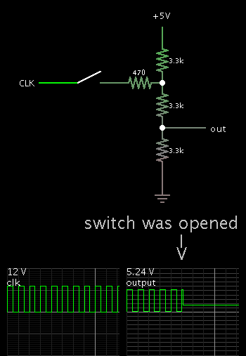
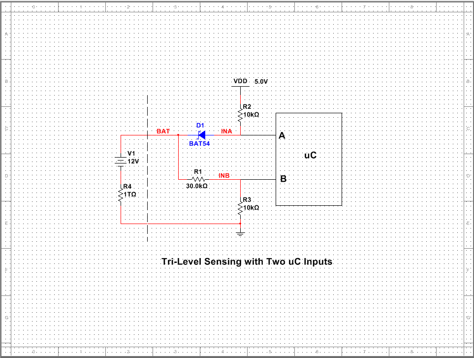
I want to detect if a signal is a logic '1' (12V) or a logic '0' (0V) on the same input pin of a PIC microcontroller.

My initial idea was to scale down the voltage using an non-inverting op-amp and then use the on-board ADC to sample the signal to see if the signal is high or low. However, the signal is not always high or low, it will be floating or high-Z most of the time.

Does anyone have a better/more simple idea?

Thanks!

Ted
 

hello,

You can use a simple divider resistors

Code:
+12V ---- 3,3 k ----|------------> ADC Pic input (<= 4,8V)
                           |
                        R=2,2K
                           |
0V-----------------|-----------> 0V

(3,3K in serial and 2,2K accross ADC input)
and check 10 bits result of ADC measure...
 

Hi paulfjujo,

Thank you for your quick response.

I tried the following: The signal is divided using a resistor divider to make a 5-0V signal. Then this is fed through a op-amp configured as a voltage follower. The output of the op-amp is then connected with the AN input of the mcu. It also has a 4k7 resistor from the output to VDD and a 4k7 resistor from the output to VSS. My thought behind this was to have a 2,5V input on the ADC when there is no signal on the input of the resistor devider. However, this does not work. The voltage is pulled low to 0,7V when there is no signal present.
 

An OP is pretty expendable for this application, but you need to pull the input signal to a level that can be clearly distinguished from 0 and 12V by a resistor, e.g. 5V.
 

Well it was a tryout. I want to know if the input is High, Low or floating. That is why I was thinking to use a resistor divider to make the input of the ADC be at 2.5V when the input is floating, 5V when the input is '1' and 0V when the input is '0'. However, my setup does not work as I described in my previous post. Anyone else got a solution for my problem?
 

Can you use two digital inputs on the uC? My idea is a resistor network and the uC supply voltage (perhaps with diodes) between the signal (0V, 12V and high impedance) and the two inputs (A and B) to generate the following logical function:


A B Voltage Source
-- -- ---------------
0 x 0V
1 0 Off
1 1 12V


It seems such a passive network should be possible. But, can you use two inputs? Also, is the voltage source low impedance? This is necessary to force voltages to change in the network.
 

Hi Analog Ground,

Yes I can use two inputs. That is not a problem. I want to detect if a signal (in a car) is pulled to 0V or to 12V.

What I thought up was to use only one analog input. When the signal is floating to read 2.5V (using a resistor divider), when the signal is high to read approx. 5V and when the signal is low to read approx. 0V. This way I can make the uC act whenever it sees a change in the state.

But using two inputs is not a problem, as long as I can detect if a signal is going from floating to low, or from floating to high.
 

You can not put the resistors on the output of the opamp - it will always be high or low - you need the resistors on the input.
Regardless you do not need the opamp at all, but rather three resistors. e.g. from 12Vdc to Gnd
12Vdc - 5.6K - 3.3K - 2.2K - Gnd
Your signal is attached to the 5.6K-3.3K junction and the PIC input to the 3.3K-2.2K junction.
Your PIC will then read (approx) 5V, 2.5V, 0V when the signal is 12V, HiZ, 0V respectively.

Depending on the PIC, output impedance of your signal, speed, and your desire to save power you can play with the resistor values.

[EDIT] Corrected resistor chain to start with 12Vdc instead of Vdd - see new reply about warning about "12Vdc" from a car electrical system
 
Last edited:

hello,


another way, with common 0V

S1 simulate floating status
3 resistors
12V -> 3.930V
0V -> 900mV
Floating-> 1200mV

in this test ADC impedance input is R4=4,7K


On_Off_Float.jpg
 

Here is my simulation, taking the resistor network described in Mike-a's post #8...

I found the output was barely more than 1V when the input was high impedance...

I adjusted values, and added another resistor at the incoming signal.


The output is close to 2V when the input is hi-Z.
 

Thank you guys for your efforts! It is awesome that you all are thinking with me!

@paulfjujo:
I will test your design as well, so far I only tested Mike-a's idea.

@BradtheRad:
In Mike-a's post #8 VDD should be at 12V (not 5V). This way his idea works perfect, I tested it and the results are exactly as he described.
 

I just edited my post to start the resistor chain at 12Vdc as I had intended (but did not do!).

The OP and I crossed posts this morning where he adds the the 12Vdc is from a car.

Car electrical systems are not very friendly, and are only nominally 12V. When the car is running the actual voltage is approx 13.8V, dipping while the engine is idling and dropping o as low as 6V while cranking.

In addition there can be ugly spikes up to 40V, because of various motors, inductors ...

so depending on what kind of 12V signal you have, you may will need to adjust resistors to be able to reduce 14Vdc to 5Vdc (resistors 3.3K and 2.2K in my network) and place transient supression across your signal or the device that is generating the signal.

The arrangement proposed by BradtheRad can be problematic because the Signal line will be supplying >2ma into the 5V supply. While that is not much, if the whole current use is less than 2 ma (not hard to do with PICs), most LDO voltage regulators can't sink current. You may need to put a load resistor (in this case 2K) accross 5V and gnd to maintain regulation

mike
 

Hi Analog Ground,

Yes I can use two inputs. That is not a problem. I want to detect if a signal (in a car) is pulled to 0V or to 12V.

What I thought up was to use only one analog input. When the signal is floating to read 2.5V (using a resistor divider), when the signal is high to read approx. 5V and when the signal is low to read approx. 0V. This way I can make the uC act whenever it sees a change in the state.

But using two inputs is not a problem, as long as I can detect if a signal is going from floating to low, or from floating to high.

Here is a resistor network with one diode to illustrate my idea of using two uC digital inputs to detect the three conditions. The table shows the logic levels and input voltages obtained. Of course, the exact voltage values needed depend on the uC used, the input logic levels and the supply voltage.


SourceABINAINB
0V0x0.25V0V
OFF104V1V
12V115V3V


The voltage source and R4 just simulate the three conditions. R4 is set to 1 ohm or 1 Teraohm to simulate 12V and OFF respectively. Then, set the voltage to 0 and R4 to 1 ohm for the 0V case.


Circuity protection needs to be added as previously posted. Certainly large value resistors in series with the inputs, etc. Also, maybe some filter capacitors to knock down transients, etc.
 
Last edited:

Status
Not open for further replies.

Similar threads

Part and Inventory Search

Welcome to EDABoard.com

Sponsor

Back
Top