Continue to Site

Welcome to EDAboard.com

Welcome to our site! EDAboard.com is an international Electronics Discussion Forum focused on EDA software, circuits, schematics, books, theory, papers, asic, pld, 8051, DSP, Network, RF, Analog Design, PCB, Service Manuals... and a whole lot more! To participate you need to register. Registration is free. Click here to register now.

Signal isolation from PE-ground.

Status
Not open for further replies.

David_

Advanced Member level 2
Joined
Dec 6, 2013
Messages
573
Helped
8
Reputation
16
Reaction score
8
Trophy points
1,308
Location
Sweden
Activity points
12,220
I have a digital two channel oscilloscope and a digital function generator both referenced to earth ground.
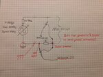
But my generator does not provide the output current i need for a couple experiments and I've built a weak ass power amplifier, not really its just a buffer BUF634 but i'm going to try out different current-boost solutions.

However i would like to do some measurements where the scope ground is not at the voltage source negative and the obvious solution would be to disconnect the generator earth reference but for one i don't see it as a viable and safe idea but as a second reason i find it really pleasing to try to solve it another way.

The output buffer can be powered from a floating source but if i don't connect the grounds i get some strange distortion on the output signal, i have seen some IC solutions but the are to expensive to buy. but there are a lot of isolators available.

Is it possible to buffer a signal that is earth ground referenced and get a floating output without one of these isolators?
I hope i can find some solution that does not require me to buy any expensive special IC, rather build my own solution with cheaper parts if possible.

Output current is a concern but i cant find a viable option to start with, can instrument amplifiers or differential amplifiers help me in some way?

Or should i aim for a homebrew differential oscilloscope probe?

The aim is to be able to treat the generator output as a floating source to take measurements from with the scope while both the scope and generator is still earth referenced.
 

If you scope has a A-B switch on it then it does not need a ground. Set both channel settings the same, switch to A-B and use both probes and read your voltage of the screen. There could be some limitation on the input level, this is called common mode rejection. For example if you are trying to measure a small volt drop across a resistor which has both ends of it sitting at 1 KV, the the 1 KV will blow up your scope. If the small volatge is sitting on a 5V level then the scope will be OK.
Unless your generator has some form of isolation transformer between it and your device under test it is extremely unlikely that you can get a generator whose output is truly floating. I would advise against removing earths on mains equipment, what will happen is that the chassis will float up to a potential of 1/2 of the mains voltage, which will appear on both output leads and cause all sorts of havoc.
Frank
 
i don't know what a A-B switch is:)
its safe to say that i have some knowledge about electronics and am looking forward to a career somewhere in the industry but i am really new to the subject and although i have ha digital oscilloscope and are known with the basics i have a lot to learn. But i understand enough ta not mess with the earth ground, even though its a bad option its a option but a rather not. I have a toroidal transformer core fore use at 50Hz which i need but is it possible to wind this as a 1:1 isolation transformer and make it a safe option?
i have read much about it but i cant find a single answer, some say its safe some say if there's a center tap grounded it safe etc etc.

the first circuit i have in mind to use is a circuit to measure the H/B properties of a transformer core, in the schematic(i will get one straight away) both scope probes ground are connected to a point that are separated from the generator ground with a resistor. one probe measures the current with the resistor and the other is measuring the voltage over a integrator passing the coil voltage.

if i would play with the idea of buying a expensive isolator, would it be possible to buffer the generator signal trough the IC and then boost the current capability? Ex ISO124P - **broken link removed**

I'm using this problem to learn about grounds in general but i think i seen some schematic somewhere(about something i don't know) but it showed two instrumentation amplifiers, one to buffer a signal and the other one to use its output as the ground/reference. I might have misunderstood the whole thing though, does that sound at all possible?

Is it a difficult exercise to design a simple low end differential scope probe? i imaging something like a well designed instrumentation amplifier with two op amps for input stage and a fully differential amplifier for output. I am willing to spend some money but say 30USD top. but that is enough for something fun as a starting block.

- - - Updated - - -

This was not drawn for this specifically but its kind of shows what my question regards .
 

Attachments

  • bil.JPG
    bil.JPG
    601.5 KB · Views: 75

What is the actual frequency (or frequency range) that you need to measure?

If your "misc circuit" is free from safety ground, you can reverse connect the chan 1 probe (so ground lead is at safety ground). You can also connect the ground lead of chan 2 probe at the safety ground. So both ground leads are connected together.

When R is very small with respect to the misc circuit impedance plus generator impedance, the additional error is likely small enough. Chan 2 probe measures sum of voltage across R and voltage across Misc circuit (so this introduces some error).

As the voltage across R is relatively small, there can be large error due to common mode to differential mode conversion in the probe. Some of the return current may go via the probe's ground (braid) back to the generator. This causes an unwanted input signal at the oscilloscope. You can use a battery powered small amplifier located very close to R to amplify the voltage across R. The otuput of the amplfier goes to chan 1 probe input and this reduces the error due to common mode to differential mode conversion.

If you are doing AC only, and there is no DC through R, you could use a so-called current transformer. This is an isolated solution and is working well up to several MHz. Above several MHz current transformers ar also possible, but the design is more critical. Note that besides the upper frequency limit, current transformers als have a lower frequency limit.
 
  • Like
Reactions: David_

    David_

    Points: 2
    Helpful Answer Positive Rating
I dropped a can of soda on my laptop and it died straight away and i haven't been able to check for answers but you certainly gave me a lot to think about, thanks.

In the mean time i have decided to finish a current probe I've been "working" on with a current transformer, I've found one in some apparatus(don't remember what) that i dissembled and i am in the process of measuring core parameters. I've read a lot about it but i have some trouble in understanding if i would get better accuracy with fewer or a higher number of turns on the secondary?
I will go through some application notes again, but i expect i will measure tings like 1mA-10mA-100mA.

It is all experimental in search for understanding, and I'm hung up on the idea of finding a way of isolating the generator output in such a way that i can treat it as a floating source if the need would arise without actually cutting the cords PE connection, i thought about how it could be done with isolation transformer at the output but then the bandwidth of that would be quite narrow would it not?

Is there a safe way of using a isolation transformer on the mains to separate the generator?
I've read a lot on the internet but nothing that makes me feel confident that it's really true, some say yes, some say no, and some say yes if the secondary(generator side) have a center-tap that is tied to PE-ground. I can't really defend why but it appears to present many interesting opportunity's regarding floating signal source related to a scope. I haven't a good enough grasp on the hole concept to know if I'm trying something close to impossible without modifying the generator internal.
 

What is your frequency range in a single measurement (as this has large influence on what to do)?

Just an example, in case of some kHz, you could use certain types of isolation transformer, but at MHz frequencies, such a transformer has no use because of capacitance between sec and prim winding, and also external wiring adds to capacitance.

The trick with the current transformer is that the secondary load impedance (resistor) should be well below the impedance (inductive) of the secondary winding for the lowest frequency that occurs in your setup. The exact ratio Zsec/Rload depends mainly on the phase error.

Please do not cut the earth lead (this also adds 0.5*mains voltage on the ground connection via the Y capacitors). So of you need a floating output (for low frequency), use an isolation transformer. In that case a single faillure in the generator would not result in mains voltage at the output terminals of the signal source. Other option is figuring out the internal DC supply voltage and use batteries.
 

Well 1Mhz would be the very most highest frequency so i guess I'm looking for a option(if available) that would cover ideally 0-1MHz, as low as i can possibly get and based on that the higher frequency range the better.

I had not considered the effect of the caps but don't worry i won't.
I'm tempted to consider if it would be feasible to re-wire the DC supply, it would present a interesting exercise.

Thanks for the transformer tip.
 

Are you really saying that you need 0..1 MHz bandwidth in a single measurement? A current transformer will not work in that case and you very likely need to incorporate all parasitics in your calculations to compensate for the effects.

If you are in wide band measurement (for example transient phenomena), then the battery supply option can eliminate the current transformer.
If you go for the battery supply for the signal source, make sure there are no connections to other equipment. If you have (for example) a serial interface that connects to your computer, your signal source is no longer floating.

I once used an air inductive coupling (running at about 1.7 MHz) to power a circuit that needed to be floating with very low capacitance to ground.
 
  • Like
Reactions: David_

    David_

    Points: 2
    Helpful Answer Positive Rating
No, I've made my self misunderstood.

The bandwidth of the measurements does not need to be 0-1MHz, I'm hopping to find a solution that will enable me to do measurements at very low freq(as low as 10 or 50Hz) and at high(1MHz) freq.
The bandwidth of the measurements wary widely but frequent frequency ranges might be:
10-100Hz
10-1000Hz
10Hz-100Khz
1kHz-10kHz
10kHz-100kHz
100kHz-1MHz

I see solutions that i could use but with my current knowledge i expect that the bandwidth of these alternatives would require me to have a few different and separate functional solutions in order to get the frequency range I'm looking for and switch between them regularly.

At first i did not want to open the generator in order to find out if i could supply it from batteries or such but it is the only solution i see, on the other hand it would really accomplish the task and allow me to experiment without many of the restraints that today holds me back. I would not have thought about that option my self, not for a while anyway.

Its a RIGOL DG1022 which is a 2 channel 20MHz/ 100MSa/s Function/Arbitrary Waveform Generator, thanks for the warning about interfaces. It could just as well have been a future situation that i on my own would have seen past, not going to be a problem.

As it is now i don't see any reason why i should not resort to supply the generator from a floating source, first i will thoroughly research the subject to get some understanding of what capability's this floating source will be required to have and how i probably will have to connect it. I imagine that its not unknown how these things usually works and although following might not be true but i should be able to get a somewhat good idea of what i will find behind the covers. First priority will be(after safety) not to mess something up, although it's a relatively cheap function generator it's a very nice and almost unused peace of equipment.
I feel very restrained by my lack of understanding, when i don't have a firm grasp on the subject it would have a big and positive impact on my learning if i could consider the signal source to be floating(when needed, it would often not be needed though).

Common sense indicates that this is not a good idea but it's a perfect exercise in order to learn about ADC and digital signal synthesis as well as it would show me something about the real world of electronic manufacturing. I'm a student and i will be insanely careful and i really can't resist not opening and taking a look inside.

But i will proceed with care and i will not open the generator until I'm sure its not a big mistake that should not be done, it's not a good idea regarding warranty but it doesn't necessarily have to be a particularly bad idea?

Although i really need to get in there in order to explore my options regarding what i will use as the floating power supply. As you point out, batteries isn't the only solution.
It takes me a while to let knowledge sink in and i might see past some important consideration.

At the same time i am proceeding with some basic tests of a current transformer with the aim to in the end build a well designed current probe.

Thanks for your input, very helpful.
 
Last edited:

For 10..10 kHz, I would use the circuit from your drawing, but with an isolation transformer at the mains. It is important that your current sensing resistor has a value well below the reactance of the capacitance of the isolation transformer.

You may extend this to say 100 kHz, but test your setup with some known impedance to rule out any strange phenomena.

For the 10 kHz to 1 MHz range, you could wind an isolation transformer in the signal path. This allows you to control your signal source via PC or other device. Of course you can use this setup at lower frequency, but this requires more turns (and increases capacitance).

Disdvantage of signal path transformer: it requires some knowlegde of transformer design. As the number of turns is relatively low, the coupling capacitance can be low (<< 200 pF), so you can use relative large current sense resistor. Also here, always check with known impedance to verify your test setup.

If you can get a mains isolated transformer and can solve the transformer in the signal path, you solve the current transformer issue (as you don't need it anymore).

Isolation transformer:
a transfomer with adjacent primary and secundary windings has lowest coupling capacitance for standard transformer shape.
There are transformers with secundary wound over the primary with an air gap in between them, but these are expensive.
A toroidal core will result in highest capacitance.
You will also find transformers that have a capacitive screen between prim and sec. This screen is connected to PE and or local ground to reject interference.
If you have two similar transformers with sufficient rating, you may connect them in series (secondary to secondary) to have a cheap isolation transformer.

- - - Updated - - -

Don't forget to discuss your proposed solution with other people around you, so we can meet you again at the forum.
 
  • Like
Reactions: David_

    David_

    Points: 2
    Helpful Answer Positive Rating
Wonderful information, i have read a lot but this kind of knowlage really puts things in appropiate context, yes i have planed to post a update when i get someware. I am in a process of geting to learn how ADD affects my thought process and although I am really focused on my goal it is rediculously difficult to hold a thread from start to finish but I'm geting there, this kind of response is invalueble in order to proceed.

I don't remember the specs but i have a toroidal core used for (50Hz) and can handle more than enough Wattage and i have a few big EI-transformers scavanged from audio amplifies and such, I have had some plans to wind a EI isolation transformer. I could then if i found appropiate copper sheet wind a inner winding covered by a grounded shield?
And then a airgap if neacesary between the shield and the outer winding.
You know those bobbins with a inner primary winding part and outer secondary winding part, I am tempted to use a core that have all E's in one stack and all I's in another stack welded together in order to save me lots and lots of time. Is there any significant difference when using those cores?

Thank you very much
 

You can wind your own, but you need lots of turn. Adding a screen (use an insulator between the copper overlap to avoid a shorted turn) is possible. Adding a thick layer of insulation (or insulating strips) before winding the secondary reduces capacitance between secondary and screen. You can use the parallel plate formula as a first guess (in real world it will be higher because of field fringe and capacitance between core legs and winding).

C = epr.r*8.854e-12*A/s [F]

here you can see that when you increase s (distance between secondary and primary) the capacitance reduces.

If you have a really large E-core transformer, you could use thinner wire for the secondary. It reduces the power rating, but it reduces copper costs and capacitance also.

If you don't want to wind one yourself, use two of your old transformers and put the secundaries to the local ground (one side only) this also acts somewhat like a screen.

Regarding the cores
If you can disassemble your EI transformer without damage, just use it, as it saves you lots of time compared to an interleaved EI core transformer. The non-interleaved transformer may have more no-load current due to the magnetic resistance at the E-I junctions. I think this is not to worry about.

For the high end of your range I would invest in the signal path transformer, as this gives lowest coupling capacitance.
 
  • Like
Reactions: David_

    David_

    Points: 2
    Helpful Answer Positive Rating
How is the weld done on those EI cores? It shoulden't allow the laminates to short together, right?

The biggest i got is the same size as a microwave owen transformer, I will digg them up to check acctual size.
How many turns are we talking about roughfly?

I've gotten it in my head that it would suffice with 300turns x 2 on a toroidal siliconiron core but that is based on nothing at all, when we are talking about a isolation transformer for 50Hz main, how does it impact the end result if i would wind a core with two windings(assume appropiate turns) without paying any attention to winding capacitance at all?

The following might not be practical but just thought about using a big battery or battery pack to drive a sine wave inverter?
Isn't there quite cheap 12Vdc to 230Vac inverters, the Generator says fuse=2A max 40W. Its not used to deliver any amounts of current.

Regarding current output, i have at the same time as everything els thought about building a more fancy current output amplifier.
When using a transformer in the signal at high freq range is it at all a appropiate idea to wind my own?

I've just got a preliminary idea of a amplifier with built in isolation transformer options, it all depend on the size needed. At high freq i assume the size won't be much of a problem but how about a low freq transformer in the signal path?

Is siliconiron or ironpowder cores a option? Say 50-500Hz

I've found winding different transformers are harder than it appears at first glance manly due to the acctual knowlage needed but that gives me a incentive to learn more about the subject, I only have a very very basic knowlage about transformers and magnetics but my intress grows constantly. Do you have any sudgestions for appropiat litterature for a beginner?
 

Status
Not open for further replies.

Similar threads

Part and Inventory Search

Welcome to EDABoard.com

Sponsor

Back
Top