Continue to Site

Welcome to EDAboard.com

Welcome to our site! EDAboard.com is an international Electronics Discussion Forum focused on EDA software, circuits, schematics, books, theory, papers, asic, pld, 8051, DSP, Network, RF, Analog Design, PCB, Service Manuals... and a whole lot more! To participate you need to register. Registration is free. Click here to register now.

How to make a desired voltage in a transistor CB amplifier?

Status
Not open for further replies.
Can you help with a transistor common base amplifier? i know how it works,

Michael, do you remember your own words?
Do you know how often you have been told in this thread that the gain has no dimension?
Nobody can help you if you don`t learn from the answers given.
 

Since the source impedance is part of the voltage gain of a common base transistor then you must measure or find out the source impedance.
Since the load impedance is part of the voltage gain of a common base or common emitter transistor then you must do the same.

The first step for designing a common base transistor with a certain amount of voltage gain is finding out the source impedance.
 

I don't get enugh Answers....but i dont understand why somebody dont tell the formula and calculation, is not enough for me because i am total begginer and is not so easy for me, maybe for you is nothing very easy
 

I have designed thousands of transistor circuits but I have never needed a common base transistor because its input impedance is too low.
What is your signal source and what is its impedance?

Maybe you need a cascode circuit instead? It is easy to calculate.
 

Attachments

  • cascode.PNG
    cascode.PNG
    17.7 KB · Views: 64

Audioguru i am total begginer ok? for me is difficult but for you is easy, let analyzie the circuit wich you make it for me, how you do calculation and formulas, just give one example with calculation and formula, the circuit wich you make, i need just one example
 

Sorry, I do not want to be a teacher of very basic electronics. I also do not want to show simple arithmetic.
Since you do not provide the signal source impedance then I think you simply want to do the arithmetic, not to make a circuit of a common base transistor.
 

The first step for designing a common base transistor with a certain amount of voltage gain is finding out the source impedance.

I rather think the first step is to know how a transistor works in the three basic configurations and how amplification is possible.
I am not sure if Michael`s knowledge of these basics is sufficient - although in his first post he says "I know how it works".
 

No Audioguru i dont want to do arithmetic

The input Impedance is 1Kohm plus re, and signal no matter, it can be 1mV of 2mV,..... so show me the arthmetics how basic is,
how can be so simpel arithmetic i dont understand.....

- - - Updated - - -

thnx for time
 

Voltage gain= 80 times. Source impedance 50 ohms. Let Re be 100 ohms and RE also be 100 ohms. Then the 50 ohm signal source is loaded with 50 ohms and is divided by 2.

Assuming no load on the output then the collector resistor value is Re x 80 x 2 which is 100 ohms x 80 x 2= 16k. The collector current in mA is 26/Re so 26/100 ohms = 0.26mA.
The supply is (16k x 0.26mA) x 2= 8.32V.
 
thank you very much for help i understand now :grin: Audioguru
 

You may be interested in watching this video I put together that describes the three basic amplifier configurations:

 
:oops: 
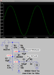
Hi Audioguru, one more time me, i try i try to make this circuit , but i dont know .... How much supply voltage we have to givet? the formula is correct, but i dont know how much voltage to give, input is not problem is easy like you say The supply is (16k x 0.26mA) x 2= 8.32V.
But i dont know how to configure circuit to work, Audioguru i am begginer
is possible for you to make one circuit with those value making to work PLEASE...:oops:

like you make this onecommon%20base%20transistor%20amplifier.png
 
Last edited:

You need to learn about transistors to design a transistor circuit. I cannot teach you.

I simulated this circuit. Its source impedance is 50 ohms.
Its voltages and voltage gain are a little different from my first calculations because all transistors are a little different from each other.

EDIT: I corrected the input signal voltage.
 

Attachments

  • common base transistor.png
    common base transistor.png
    22.1 KB · Views: 64
Last edited:
Whats your problem michael 1978?, build your circuit and use a 9V supply, it will work. Once you have measured the gain with your ACTUAL source impedance and load impedance, then you might have to think again. Reduce the collector load for less gain. If you need more gain , increase the collector load, but you may end up with not enough voltage across the transistor for it to work properly, if so, reduce the value of the 2k2 resistor until the transistor has, say 4V emitter to collector.
Frank
 
Thank you for time Audioguru it :grin:
 

Status
Not open for further replies.

Similar threads

Part and Inventory Search

Welcome to EDABoard.com

Sponsor

Back
Top