Continue to Site

Welcome to EDAboard.com

Welcome to our site! EDAboard.com is an international Electronics Discussion Forum focused on EDA software, circuits, schematics, books, theory, papers, asic, pld, 8051, DSP, Network, RF, Analog Design, PCB, Service Manuals... and a whole lot more! To participate you need to register. Registration is free. Click here to register now.

Input/Output impedance - single transistor Class A amplifier and emitter follower

Status
Not open for further replies.

juz_ad

Full Member level 2
Joined
Dec 17, 2011
Messages
130
Helped
0
Reputation
0
Reaction score
0
Trophy points
1,296
Activity points
2,541
Taking my first steps with simple, single transistor Class A designs.

Can anyone give me a gentle intro to how the input and output impedance is set/calculated on the standard single transistor amp in class A configuration and the single transistor emitter/voltage follower?

Thanks,

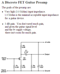
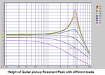
[Edit] I'm working towards a guitar-based project so I'm currently aiming at an input Z of approx. 1M and an output Z of approx. 10K - I think...

- J
 
Last edited:

You need a Jfet, not an ordinary transistor to have an input impedance as high as 1M. Or you can probably use two transistors with the second transistor bootstrapping the input of the first transistor. Here is a typical guitar preamp circuit:
 

Attachments

  • guitar preamp.PNG
    guitar preamp.PNG
    15.4 KB · Views: 123

Thanks - so in the schematic above is the input impedance set just by R1 or R1||R2 or by R1||R2||R3?

This is very similar to the EHX LPB1 Booster - which uses a PNP transistor.
 

The input impedance of the Jfet is infinity so the input impedance of the circuit is R1 which is 3M ohms.
An ordinary transistor has a fairly low input impedance.

A guitar preamp must have a very high input impedance for the inductance of the magnetic pickup to resonate at about 4.5kHz with the capacitance of the cable and produce a peak in the frequency response which creates the "twang" sound. A low impedance muffles the high frequencies so everything sounds like a telephone or like how a deaf person (a guitar player in a band?) would hear.

The EHX LPB-1 Booster circuit is shown in Google using an NPN ordinary transistor. The input impedance of the circuit is fairly low so it cuts most high audio frequencies.
 

Attachments

  • LPB-1 guitar booster.png
    LPB-1 guitar booster.png
    23.4 KB · Views: 111
  • Guitar pickup peak.PNG
    Guitar pickup peak.PNG
    73.1 KB · Views: 97
  • Like
Reactions: juz_ad

    juz_ad

    Points: 2
    Helpful Answer Positive Rating
Thanks - that's really helpful and confirms that the input impedance on the second schem you posted is set by R1 || R2 || R4.

6930974800_1393015826.png


Can I ask - on this version of the same circuit - is the input impedance set by R13 (the 100k to GND)?

Thanks again - much appreciated.
 

Your new circuit with the 2N3904 transistor has a fairly low input impedance due to the negative feedback through R11 to the input.
I simulated it. With a transistor with a typical hfe its input impedance is only 22k ohms and is lower if the transistor has minimum hfe.
The value of the input capacitor is very low which cuts low frequencies.
 

Can I ask how you calculated that?
I didn't calculate it, instead I simulated it. The simulation program uses a transistor with typical hfe.
I never bias a transistor like that with a feedback resistor because the negative feedback (and therefore the voltage gain) through the biasing resistor depends on the source impedance.
 

Can I ask how you calculated that?
Thanks.

The input impedance results from the parallel combination of the following contributors:
* R19=100k
* (hie+hfe*R12) (hie=rbe, hfe=current gain)
* R11/(1+|A|) with A=voltage gain, which is roughly A=-g*R9/(1+g*R12) with g=hfe/hie.
(Miller effect for R11).
* Comment: The above gain formula assumes a signal source with a source impedanze Zin=0, see Audioguru´s comment.
 

Status
Not open for further replies.

Part and Inventory Search

Welcome to EDABoard.com

Sponsor

Back
Top