dtothec
Newbie level 3
Hello all. Obviously I'm new here so I hope this is in the right place. My friend recommended posting here, he said it really helped him out so here I go.
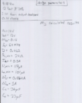
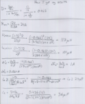
I have been trying to design a Cuk Converter that will take in an input voltage of 9-18V and give an output of 12V (+/- 20%). The output voltage ripple across the outout capacitor C0 needs to be 0.1V. I have little to no experience with converters but I was able to workout values for all of the resistors, inductors, and capacitors for the circuit. Currently I have left out the feedback for the system in order to focus on the converter itself. For the initial design I have set the the input voltage to 14V and the switching transistor is ran by a square wave with a peak voltage of 10V.
The problem is that something doesn't work. When I run the simulation the output voltage comes out to be 82.97e-24V. I'm not very confident with PSpice, so I may be using the wrong parts, or my calculations could be incorrect. In short I would like to know which is wrong, my schematic or my calculations? That way I can go about fixing it.
When designing the circuit I made a few assumptions (these are not set in stone)
1) I set the output current Ia = 0.5A
2) I set ΔVCt = 0.1V
Below I have attached my hand worked calculations and a picture of the schematic.
Thank you all for the help,
dtothec


Edit: So I measured the voltage across the load resistor and it turns out it works. So for now everything is good.
I have been trying to design a Cuk Converter that will take in an input voltage of 9-18V and give an output of 12V (+/- 20%). The output voltage ripple across the outout capacitor C0 needs to be 0.1V. I have little to no experience with converters but I was able to workout values for all of the resistors, inductors, and capacitors for the circuit. Currently I have left out the feedback for the system in order to focus on the converter itself. For the initial design I have set the the input voltage to 14V and the switching transistor is ran by a square wave with a peak voltage of 10V.
The problem is that something doesn't work. When I run the simulation the output voltage comes out to be 82.97e-24V. I'm not very confident with PSpice, so I may be using the wrong parts, or my calculations could be incorrect. In short I would like to know which is wrong, my schematic or my calculations? That way I can go about fixing it.
When designing the circuit I made a few assumptions (these are not set in stone)
1) I set the output current Ia = 0.5A
2) I set ΔVCt = 0.1V
Below I have attached my hand worked calculations and a picture of the schematic.
Thank you all for the help,
dtothec


Edit: So I measured the voltage across the load resistor and it turns out it works. So for now everything is good.
Last edited: