Continue to Site

Welcome to EDAboard.com

Welcome to our site! EDAboard.com is an international Electronics Discussion Forum focused on EDA software, circuits, schematics, books, theory, papers, asic, pld, 8051, DSP, Network, RF, Analog Design, PCB, Service Manuals... and a whole lot more! To participate you need to register. Registration is free. Click here to register now.

Selectable Voltage Output or Current Output reading

Status
Not open for further replies.

kitepassion

Member level 3
Joined
Jan 5, 2010
Messages
54
Helped
0
Reputation
0
Reaction score
0
Trophy points
1,286
Location
US
Activity points
1,659
Hi all,

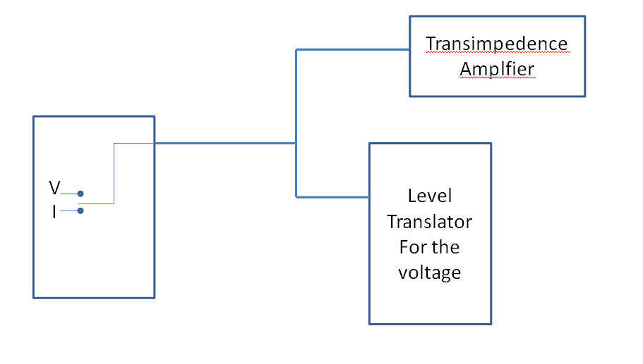
I have a sensor with a configurable pin. It can be configured to have a voltage output or a current output. They are not the same in the sense that the current is not the translation of the voltage. So I want to clearly be able to measure both of them but without affecting their value. I do not want to affect the current measurement when measuring the voltage and vice-versa.
I need to use a level translator for the voltage reading.
Is the solution provided in the image good? Can you suggest me another solution?

Thank you!


Is the solution provided in the image good?
I don't reconize a solution, neither a clear problem specification.

At first sight, a transimpedance amplifier will short an input voltage, so how is the "level translator" supposed to work?

Generally, a current source (sensor with current output, e.g. 0 - 20 mA) generates a voltage when connected to a load and a voltage source (sensor with voltage output, e.g. 0 - 10 V) has an output resistance and generates a current when loaded.

So how does your measurement circuit know if the sensor is operating in voltage or current mode?
 

Sorry for the poor specification.

The switch that you see in the sensor is driven by a microcontroller which decides to read a value of voltage from one sensor or a current from another sensor embedded.
So I need at least a switch between the two paths (transimpedence and voltage translator) to de-couple them. Right?

Cheers
 

So I need at least a switch between the two paths (transimpedence and voltage translator) to de-couple them. Right?

Yes. You didn't say if the current measurement is expected to have "zero" voltage drop and must use a transimpedance circuit. If so, there must be a series switch to disconnect the I/V converter. The voltage measurement path can be always connected if it uses a high impedance buffer.

We might ask why you have the front I/V mux and don't use dedicated I and V channels?
 

We might ask why you have the front I/V mux and don't use dedicated I and V channels?

The sensor is like this.. I have one channel for I and V with a digital circuit from which I can decide the output I want. Yes the current has zero drop the transimpedence amplifier is needed.

Could I use a BST82 as a switch to deconnect the transimpedence amplifier?

Cheers
 

Status
Not open for further replies.

Similar threads

Part and Inventory Search

Welcome to EDABoard.com

Sponsor

Back
Top