Continue to Site

Welcome to EDAboard.com

Welcome to our site! EDAboard.com is an international Electronics Discussion Forum focused on EDA software, circuits, schematics, books, theory, papers, asic, pld, 8051, DSP, Network, RF, Analog Design, PCB, Service Manuals... and a whole lot more! To participate you need to register. Registration is free. Click here to register now.

PIC to Pic communication Through RF module

Status
Not open for further replies.

ranakashif

Newbie level 6
Joined
Feb 7, 2014
Messages
13
Helped
1
Reputation
2
Reaction score
1
Trophy points
3
Activity points
93
Hi,
I want to get value of Temperature from temperature sensor and by using ADC of Pic I want to send it to other Pic U controller using XBee module.please tell me how to interface pic with Xbee.I need your help.
my circuit for temperature sensor is this.
Circuit.jpg
 

First read the Temperature senor's value and print it in LCD ,

Then It's kind of thing your first part is cleared ,

Now we come at Zig-bee , Download X-CTU from Digikey Website ,
Then take two X-Bee Modules Declare one as CoORDINATOR ""API"" & another as same as ""AT""

Basically Check with PC only using UART to USB and check for the communication Between two X-Bee Modules

If the Communication is successful

So Do same with the PIC Microcontroller (interfaced with X-Bee) using UART send some data like any character 'A' and Check in the Other end's PIC microcontroller ((interfaced with ANOTHER X-Bee),
and then if this portion is successful ,
then Read ADC Value and send that Value using UART Tx of 1st PIC connected to X-bee only and then at the other end read that Value using ANOTHER X-bee and print that Value to 2nd LCD connected to 2nd PIC
 
I used Pic16f877A ucontroller and lm35 (temperature sensor). and take temperature value in proteus but on breadbord only switch on the Lcd and black square appears but output does not shoes. I used mikroC Pro for programming.

code is given below.
Code:
                       // Lcd pinout settings
sbit LCD_RS at RC6_bit;
sbit LCD_EN at RC7_bit;
sbit LCD_D7 at RC3_bit;
sbit LCD_D6 at RC2_bit;
sbit LCD_D5 at RC1_bit;
sbit LCD_D4 at RC0_bit;

sbit LCD_RS_Direction at TRISC6_bit;
sbit LCD_EN_Direction at TRISC7_bit;
sbit LCD_D4_Direction at TRISC0_bit;
sbit LCD_D5_Direction at TRISC1_bit;
sbit LCD_D6_Direction at TRISC2_bit;
sbit LCD_D7_Direction at TRISC3_bit;

unsigned long ADRead;
unsigned int vDisp[3];
unsigned char Display[7];

void main() {

     PORTA = 0;
     TRISA = 0X01;
     PORTC = 0;
     TRISC = 0;
     LCD_Init();
     LCD_Cmd(_LCD_CURSOR_OFF);
     LCD_Cmd(_LCD_CLEAR);
     LCD_Out(1, 1, "Temp:");
     //Display = "+125 'C";
     Display[4] = 39; //'
     Display[5]= 'C';
     ADCON1 = 0x0E;
     ADC_Init();
     while (1){
           ADRead = (ADC_Get_Sample(0) * 0.4883);     //from 500
           vDisp[0] = ADRead / 100;
           vDisp[1] = (ADRead / 10) % 10;
           vDisp[2] = ADRead % 10;
           Display[1] = vDisp[0] + 48;   // I changed 48 to 70 for checking
           Display[2] = vDisp[1] + 48;
           Display[3] = vDisp[2] + 48;
           LCD_Chr(1, 8, Display[0]);
           LCD_Chr(1, 9, Display[1]);
           LCD_Chr(1, 10, Display[2]);
           LCD_Chr(1, 11, Display[3]);
           LCD_Chr(1, 12, Display[4]);
           LCD_Chr(1, 13, Display[5]);
           //LCD_Out(1, 8, ); // 'Show temperature
           delay_ms(200); //200ms delay for waiting
     }
}
 
Last edited by a moderator:

Showing temperature on Lcd using ADC of Pic 16f877A

hi,
I Want to measure temperature value from LM35 temperature sensor by using ADC of PIC16f877A. I made circuit in Proteus. I used this code. It is working in Proteus but on breadboard only Lcd back light on and black squares appear but output does not shows. I used 8MHz crystal. please help me to solve this issue.
Temperature.jpg
code is given below.

Code:
                       // Lcd pinout settings
sbit LCD_RS at RC6_bit;
sbit LCD_EN at RC7_bit;
sbit LCD_D7 at RC3_bit;
sbit LCD_D6 at RC2_bit;
sbit LCD_D5 at RC1_bit;
sbit LCD_D4 at RC0_bit;

sbit LCD_RS_Direction at TRISC6_bit;
sbit LCD_EN_Direction at TRISC7_bit;
sbit LCD_D4_Direction at TRISC0_bit;
sbit LCD_D5_Direction at TRISC1_bit;
sbit LCD_D6_Direction at TRISC2_bit;
sbit LCD_D7_Direction at TRISC3_bit;

unsigned long ADRead;
unsigned int vDisp[3];
unsigned char Display[7];

void main() {

     PORTA = 0;
     TRISA = 0X01;
     PORTC = 0;
     TRISC = 0;
     LCD_Init();
     LCD_Cmd(_LCD_CURSOR_OFF);
     LCD_Cmd(_LCD_CLEAR);
     LCD_Out(1, 1, "Temp:");
     //Display = "+125 'C";
     Display[4] = 39; //'
     Display[5]= 'C';
     ADCON1 = 0x0E;
     ADC_Init();
     while (1){
          ADRead = (ADC_Get_Sample(0) * 0.4883);
           vDisp[0] = ADRead / 100;
         vDisp[1] = (ADRead / 10) % 10;
           vDisp[2] = ADRead % 10;
           Display[1] = vDisp[0] + 48;
          Display[2] = vDisp[1] + 48;
          Display[3] = vDisp[2] + 48;
           LCD_Chr(1, 8, Display[0]);
           LCD_Chr(1, 9, Display[1]);
          LCD_Chr(1, 10, Display[2]);
           LCD_Chr(1, 11, Display[3]);
           LCD_Chr(1, 12, Display[4]);
           LCD_Chr(1, 13, Display[5]);
            //LCD_Out(1, 8, ); // 'Show temperature
           delay_ms(200); //200ms delay for waiting
     }
}
 

Re: Showing temperature on Lcd using ADC of Pic 16f877A

...on breadboard only Lcd back light on and black squares appear but output does not shows...

How are you biasing contrast adjust pin of LCD ?
At above circuit, seems as unconnected.


+++
 
Re: Showing temperature on Lcd using ADC of Pic 16f877A

hello

Try to add a delay of 500mS before lcdinit
to wait power on stabilisation..
 

Re: Showing temperature on Lcd using ADC of Pic 16f877A

I have changed the biasing of contrast adjust pin of Lcd but output does not shows. please tell me that is there any error in configuration of ADC module?
 

Re: Showing temperature on Lcd using ADC of Pic 16f877A

A HD44780 based or compatible LCD display requires a proper amount of time to powerup, initialize and arrive at a known state.

If you display resembles the following:


It usually indicates the LCD was not allowed to powerup and initialize properly before input was received.

Typically a 50ms delay will suffice, insert the appropriate delay routine before the LCD_Init() statement.

How did you bias VEE?

Typically a 10kΩ pot is utilized, with the wiper attached to VEE and the remaining terminal to VDD and VSS.

Also, are you sure the LCD library currently being utilized supports a 4-bit interface?


BigDog
 
Re: Showing temperature on Lcd using ADC of Pic 16f877A

Connect pull up resisters on pins that connected to lcd.
Try this code posted below it shall work
 

Attachments

  • 2 lcd.rar
    49.4 KB · Views: 87
Re: Showing temperature on Lcd using ADC of Pic 16f877A

Connect pull up resisters on pins that connected to lcd.

The use of pull resistors is typically only necessary when the I/O pins of the microcontroller are open collector/drain.


BigDog
 
Re: Showing temperature on Lcd using ADC of Pic 16f877A

Agreed with @bigdogguru
If display resembles the image uploaded by him, it is exactly the same issue because i faced it...!
 
Re: Showing temperature on Lcd using ADC of Pic 16f877A

I have connected 4.7k resistors with four pins of ucontroller which are connected to LCD but output does not shows.
 
PIC16f877A UART with XBee pro s1

Hi,
I want to interface XBee pro s1 with PIC16f877A.I want to transmit temperature Value through XBee pro s1 to other XBee .I used Lm35 temperature sensor and PIC16f877A. How to configure UART.please help me to solve this issue.
 

Re: PIC16f877A UART with XBee pro s1

Transmitter code.


Code C - [expand]
1
2
3
4
5
6
7
8
9
10
11
12
13
14
15
16
17
18
19
20
21
22
23
24
25
26
27
28
29
30
31
32
33
34
35
36
37
38
39
40
41
42
43
44
45
46
47
48
49
50
51
52
53
54
55
56
57
58
59
60
61
62
63
// Lcd pinout settings
sbit LCD_RS at RC6_bit;
sbit LCD_EN at RC7_bit;
sbit LCD_D7 at RC3_bit;
sbit LCD_D6 at RC2_bit;
sbit LCD_D5 at RC1_bit;
sbit LCD_D4 at RC0_bit;
 
sbit LCD_RS_Direction at TRISC6_bit;
sbit LCD_EN_Direction at TRISC7_bit;
sbit LCD_D4_Direction at TRISC0_bit;
sbit LCD_D5_Direction at TRISC1_bit;
sbit LCD_D6_Direction at TRISC2_bit;
sbit LCD_D7_Direction at TRISC3_bit;
 
float ADRead, oldVal = 0.0;
unsigned char display[23];
 
const char character[] = {6,9,9,6,0,0,0,0};
 
void CustomChar(char pos_row, char pos_char) {
  char i;
    Lcd_Cmd(64);
    for (i = 0; i<=7; i++) Lcd_Chr_CP(character[i]);
    Lcd_Cmd(_LCD_RETURN_HOME);
    Lcd_Chr(pos_row, pos_char, 0);
}
 
void main() {
 
     TRISA = 0x01;
     PORTA = 0x00;
     TRISC = 0x80;
     PORTC = 0x00;
     ADCON1 = 0x0E;
 
     LCD_Init();
     LCD_Cmd(_LCD_CURSOR_OFF);
     LCD_Cmd(_LCD_CLEAR);
     LCD_Out(1, 1, "Temp: ");
 
     UART1_Init(9600);
     Delay_ms(200);
              
     while (1){
 
          ADRead = ADC_Read(0) * 0.4883;
 
         if(oldVal != ADRead) {
    
            FloatToStr(ADRead, display);
            display[8] = '\0';
            LCD_Out(1, 7, display);
            CustomChar(1, 15);
            LCD_Out(1, 7, "C");
            strcat(display, "\r\n");
            UART1_Write_Text(display);      
            oldVal = ADRead;
          }  
            
          Delay_ms(200); 
     }
}

 
@RanakShif :: Have you connected POT output on PIN no.3 (CONTRAST pin of LCD) Try to attach a 10k value POT and check for the BLACK Dot Matrix Appearance ,
then it will be lowered in Contrast it may happen there that Your text is printing but due to the High Contrast it is Not Visible

then Also Check For the R/W Pin it should be to Ground or assign to a pin which have LOW Logic in Both When it is sending Command or Data
Try these steps and tell if you face any Problem
 

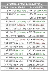
Properly configuring the UART of the PIC16F877A depends on the system clock frequency (FOSC) of the current design.

Also be aware some FOSC are not appropriate for generating specific baud rates, you must keep the baud rate error at or below acceptable levels.


PIC Microcontroller RS232 I/O SPBRG Calculator

Both the UART of the PIC and the Receiving device must match the UART settings of the XBee Pro Series 1.

The XBee Pro Series 1 devices do not support the ZigBee protocol, they only support 802.15.4 and the proprietary DigiMesh 2.4 Protocols.

XBee Pro Series 1 802.15.4 Documentation

Of course, this is not an issue as the 802.15.4 protocol is fine for setting up a point-to-point virtual serial cable.

What type of device is the other XBee Pro Series 1 connected?

What is the current device configuration of the XBee Pro Series 1 devices, Baud Rate, etc?


BigDog
 
Hi,
Thanks to all of u for helping me a lot.

I have read the value from Lm35 Temperature sensor and displayed on lcd. now I want to to transmit this value to other microcontroller through XBee s1. I have bought two Xbee s1. I have checked these individually with Hyperterminal and X-CTU software. These are responding well. now I want to communicate two XBee forming a simple network with PC. After that I want to interface XBee with PIC16f877A to transmit temperature value to othe PIC because XBee works on 3.3v. How to do this?Please help me in this regard.
The Image of XBee is given below.
 

I have a project where 2 xbee is used.one is connected to pc using pic18f4550 and another is is collecting adc samples send it to receiver xbee.I get the book very helpful named Building Wireless Sensor Networks by Faludi.

To show the value of lm35 in lcd you can take look to this tutorial.
**broken link removed**
 

Status
Not open for further replies.

Part and Inventory Search

Welcome to EDABoard.com

Sponsor

Back
Top