soundquist
Newbie level 2
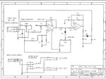
Hello, simple nube question here, first a bit about myself, I am a circuit bender of keyboards, I have a good general understanding of electrical components and their functions. I recently have been commissioned to build a pedal to control the rotation speed of a rotary speaker (a "Motion Sound Gas Pedal," no longer produced). I feel I am up to the task and have found the proper schematic which is attached to this post. I understand the upper portion of the diagram just fine but am somewhat new to this and puzzled by the detached section at the bottom. C1 and C2 are used heavily, I am wondering how to attach the bottom portion with the top.
I get the DPDT switch and the jacks, I am just wondering how to hook up the bottom module with the top, i.e. which side of the polarized capacitors (C1,2,3..) to connect to and how to handle their multiple implementations. I assume current runs from left to right here (+ to -), but whats the deal with C4 and C2 being in line for the amplifier jack? Sorry if my questions are confusing or don't belong here, please clarify this for me.
I get the DPDT switch and the jacks, I am just wondering how to hook up the bottom module with the top, i.e. which side of the polarized capacitors (C1,2,3..) to connect to and how to handle their multiple implementations. I assume current runs from left to right here (+ to -), but whats the deal with C4 and C2 being in line for the amplifier jack? Sorry if my questions are confusing or don't belong here, please clarify this for me.