Continue to Site

Welcome to EDAboard.com

Welcome to our site! EDAboard.com is an international Electronics Discussion Forum focused on EDA software, circuits, schematics, books, theory, papers, asic, pld, 8051, DSP, Network, RF, Analog Design, PCB, Service Manuals... and a whole lot more! To participate you need to register. Registration is free. Click here to register now.

[SOLVED] Burglar Alarm Circuit

Status
Not open for further replies.
I think you must learn about the TSOP IR receiver:
The base of your transistor Q1 will hold its output at a low voltage which is wrong as is said on its datasheet.
The TSOP and transistor are turned on by an IR beam. When the burglar blocks the beam then the transistor turns off then the trigger pin 2 of the 555 goes HIGH.

I think you must learn about the 555. It is triggered when its pin 2 goes LOW (when the burglar is gone). Then the buzzers sound and the timer begins. But it will never timeout because pin 2 is held low by transistor Q1.

You are wrong there. The datasheet of the TSOP4038 states that it's output is active LOW i.e. when IR beam is falling on it, it outputs a LOW (0V) to the base of transistor Q1, as a result, Q1 behaves like an open switch and the trigger input is held high.

When the path of IR beam is broke, the receiver outputs HIGH (5V), which turns on the transistor Q1, it now behaves like a closed switch, so the trigger input is pulled low and the timer starts functioning.
You are correct, I was wrong.

I don't know why but the datasheets of many TSOP IR receivers say, "The output voltage VO should not be pulled down to a level below 1 V by the external circuit."
The base of your transistor is pulling down the output of the IR receiver to about +0.7V.
 

Yes, a little confusing. When the output is active LOW, why should any external circuit pull it down to a level below 1V ? I'll build it on a breadboard today or tomorrow, just waiting for the parts to arrive, then I'll post the results. Thank you Audioguru for helping me so much in this topic :)
 

Here comes the kicker, neither of the three receivers, TSOP4038, TSSP58038, and TSSP6038 is available in my city, so I'm going to shelf the project, as I cannot see any other hope...
 

The output voltage VO should not be pulled down to a level below 1 V by the external circuit."
I've asked the Vishay tech supports why they have this recommendation in the datasheet, as from the block diagram of the output stage and the max ratings and electrical characteristics there's no obvious reason for it. Also I pointed out that the recommendation is no present for the spec of the newer, but otherwise near identical replacement, TSSOP4038. Here's their verbatim response:
At the new TSSP4038 you can pull the output voltage to any value between 0V and Vs without impact to the function.
At the old TSOP4038 you could activate a standby mode when you pull the output to a level lower than 0.7V. In that case the device won't function in the normal way but there is no risk for damaging it.
Shame there's no further details provided anywhere as to the nature and function of this "standby mode"!

I can also say that (prior to noticing this recommendation hidden away in the spec sheet) I built 6 light curtains consisting of 8 TSOP4038's each, running at 3.3V. Pin 1 of each is connected directly to the base of a BC547 to drive a common active high signal line that is pulled up to 3.3V. Given the output stage in the block diagram with the 33k pullup, omitting the base resistor seemed perfectly acceptable at the time....

I've never encountered any side effects of this mysterious standby mode, and my design is working perfectly. But them of course Vbe of the BC547 is around 0.7V anyway - still very close for comfort! Perhaps the 0.7V is at the max 5.5V and proportionally lower at lower supply voltages? That would equate to 0.42V at 3.3V.
 

Vishay-Telefunken is in Germany so maybe the details of the "standby mode" is on German datasheet.
The TSOP1138 and TSOP1738 datasheets say do not hold the output continuously below 3.3V. The TSOP4038 datasheet says 1V.
 

I couldn't find anything in German. But here's a little details from the Circuit Description Document:
As shown in figure 1, the digital output of the TSOP IR receiver modules is an open collector transistor with an internal pull up resistor. An additional external pull up resistor can optionally be used if more current is needed to drive the input of the decoding device or if a faster switching time is required. The logic low level will be below 0.2 V even at a sink current of 2 mA. The output can continuously drive a capacitance of up to 1 nF without risk of damaging the output stage.
If is not recommended to pull down the output of the IR receivers to a voltage below 1 V by a pull down resistor or any other external components. Some IR receiver types might not work properly in that condition because a standby mode is activated.
Still not a lot of help. Especially the "Some IR receiver types" and "might not" - ok, which, when?
And how does the standby mode work exactly?

I've asked them if they can clarify, because having already constructed 48 of these it isn't easy to go reworking them!
 

pcbbc and Audioguru,

After trying in vain to find the TSOP4038 in my area, I've decided to ask Vishay to send 2-3 samples. Can you tell the procedure and costs regarding this matter ?
 

I have never asked for a free sample of an electronic part since everything is available at a low cost from Digikey or Newark.
Today, Digikey never heard about the TSOP4038 but Newwark has 3200 of them in stock for $.68 each.
 

No idea - we don't work for Vishay here, or have anything to do with them. Mine cost me about 70 pence (0.70 GBP) each from RS Components here in the UK. I probably have some spares, but postage might be the killer. PM me if Vishay can't help you.

I do have a reply from Vishay technical support, which says that the standby mode was never particularly effective at saving power, so details of it were excluded from the datasheet. But it seems that pulling the output below 0.6V (min 0.3V, max 0.85V) should mean that the device enters standby and will no longer responding to IR signals until it is released. It's expected that the microprocessor should periodically release the data line, to listen for an incoming IR signal and also that the sending device should send a burst of IR as a wakeup signal prior to any "data". The burst obviously has to be longer than the periods for which the uP pulls data low in order to not miss the start of the data.

Given that the primary application of the TSOP4038 is as a light curtain, I question the usefulness of a power saving mode anyway!
 

Sorry to mark this post as UNSOLVED after marking it solved. I thought it was a dead end, but there seems a ray of hope.

Working on another project, I came across HT12E and HT12D chips. Then it occurred to my mind, if I can drive the reset pin of a 38KHz astable multvibrator using timer 555, then transmit the signal with an IR Led.

The receiver section will be containing a TSOP1738 which will drive the Din pin of HT12D through a transistor. The Vt pin of the HT12D drives the trigger pin of the monostable timer 555... will it work ? Or am I missing something ?
 

The TSOP1738 has automatic gain control that reduces its gain a lot when it receives continuous 38kHz interference (from a modern compact fluorescent bulb). Its gain stays high if it receives "bursts" of 38kHz as explained in its datasheet and is provided by remote controls sending data.
 

Yes, that's what I'm going to do with the help of HT12E, I will send a 7 bit code using 38Khz IR...
 

Okay... hooked up the circuit on a breadboard, as expected, it doesn't work !! I have pin-pointed the problem, most probably the timer is not generating 38Khz carrier wave. I don't have an oscilloscope. I'm using R1=22K and R2=7.5K and C=0.001uF, is there any way I can check whether it is generating 38Khz ?
 

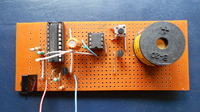
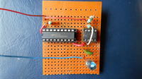
Okay so the project got WAY delayed due to academics... But finally it's done... And it works like a charm !! Thanks to all the members who commented on this post, especially Audioguru, for helping me out on this topic !!

The Circuit on the left is the receiver and the circuit on the right is the transmitter....


I'm marking this topic as solved...
 

Status
Not open for further replies.

Similar threads

Part and Inventory Search

Welcome to EDABoard.com

Sponsor

Back
Top