Continue to Site

Welcome to EDAboard.com

Welcome to our site! EDAboard.com is an international Electronics Discussion Forum focused on EDA software, circuits, schematics, books, theory, papers, asic, pld, 8051, DSP, Network, RF, Analog Design, PCB, Service Manuals... and a whole lot more! To participate you need to register. Registration is free. Click here to register now.

control system, poles and stability response

Status
Not open for further replies.

MissP.25_5

Newbie level 6
Joined
Nov 25, 2013
Messages
11
Helped
0
Reputation
0
Reaction score
0
Trophy points
1
Activity points
87
Can you help me compare these results? They're the simulations of a closed loop system . When we change the poles, (in this case, there are 4 poles), the response system also changes. The 4 poles involves 2 complex numbers and 2 integers, but I don't see the relationship between the poles and the response. I don't see an exact description. I mean, a description like:
if the real number is increased, then the response would be more oscillatory or if the imaginary part is smaller, then the faster the convergence to 0.
Help, please?
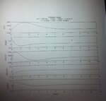
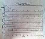
IMG_5371.JPGIMG_5372.JPGIMG_5374.JPG
 

Can you help me compare these results? They're the simulations of a closed loop system . When we change the poles, (in this case, there are 4 poles), the response system also changes. The 4 poles involves 2 complex numbers and 2 integers, but I don't see the relationship between the poles and the response. I don't see an exact description. I mean, a description like:
if the real number is increased, then the response would be more oscillatory or if the imaginary part is smaller, then the faster the convergence to 0.
Help, please?


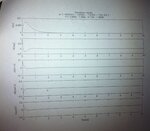
Hi MissP.25_5

I don't see anything surprising ! when you change location of poles of a circuit response of a circuit will be involved by some changes which depends on where are the poles exactly .

A suitable Article from MIT can lead you through a good understanding :

https://www.google.com/url?sa=t&rct...49rrizoE36gbkCaBRbdfLyg&bvm=bv.56988011,d.cGU


Best Wishes
Goldsmith

Yes, that's what I said. The response depends on the poles. But I need to compare these 3 results. They're the results of 3 different poles. I also need to write the relationship between the complex numbers and the response. Can you help?
 

MissP - it is not easy to answer your question because it is not clear which parameters of the closed-loop sysytem are shown.
Watching the first line I see something like a step response, correct?
In this context, I am confused about the last line showing an input. Which input?

As a general (and preliminary) answer:
A complex pole pair causes overshoot in the step response. When the (negative) real part of these poles come closer to the origin (imag. parts constant) the overshoot increases.
Moreover, a negative real pole (at s=-sigma) causes a damping of the step response corresponding to exp(-sigma*t). Thus, the duration of the step response is inverse proportional to sigma.
I think, the time response (first line) can confirm these statements.
 
Last edited:
MissP - it is not easy to answer your question because it is not clear which parameters of the closed-loop sysytem are shown.
Watching the first line I see something like a step response, correct?
In this context, I am confused about the last line showing an input. Which input?

As a general (and preliminary) answer:
A complex pole pair causes overshoot in the step response. When the (negative) real part of these poles come closer to the origin (imag. parts constant) the overshoot increases.
Moreover, a negative real pole (at s=-sigma) causes a damping of the step response corresponding to exp(-sigma*t). Thus, the duration of the step response is inverse proportional to sigma.
I think, the time response (first line) can confirm these statements.

The input is the voltage input used to produce the torque for the pendulum arm to oscillate. The poles consist of 2 pair of real numbers and 2 pairs of conjugate numbers. What do the real numbers say about the response?
 

The input is the voltage input used to produce the torque for the pendulum arm to oscillate. The poles consist of 2 pair of real numbers and 2 pairs of conjugate numbers. What do the real numbers say about the response?

Sorry to say but your answers do not clarify things.
However, at least I have learned that the system input is NOT a voltage step - correct?
In this case, it is rather complicated to verify/justify/explain the system response.
 
Status
Not open for further replies.

Part and Inventory Search

Welcome to EDABoard.com

Sponsor

Back
Top