Continue to Site

Welcome to EDAboard.com

Welcome to our site! EDAboard.com is an international Electronics Discussion Forum focused on EDA software, circuits, schematics, books, theory, papers, asic, pld, 8051, DSP, Network, RF, Analog Design, PCB, Service Manuals... and a whole lot more! To participate you need to register. Registration is free. Click here to register now.

cc1101 transceiver guidance for PIC MCU

Status
Not open for further replies.

muhammadali_16

Full Member level 3
Joined
Jul 15, 2011
Messages
161
Helped
0
Reputation
0
Reaction score
0
Trophy points
1,296
Activity points
2,335
hiz to all.

i need to use cc1101 to have RSSI extracted. i have searched alot for the code but couldnt found for pic MCU.

can anyone just guide me how to do this. i am not understanding from where i could start to do this.

i am using mikroc compiler. but also comfortable with other compiler.

waiting for response
 

Except for the basic SPI interface setup, there won't be much PIC specific in the code.

RSSI information can be appended to the RX packet or read separately read from a status register, as described in the datasheet.
 

can you just tell me the flow of the code for both transmission and receiving. what i understand is

header files
initailize spi
send all the register values (have seen in many places)
send and receive commands
RSSI
end

kindly also mention how to set transceiver to transmitting and receiving mode

Thanks in advance

Except for the basic SPI interface setup, there won't be much PIC specific in the code.

RSSI information can be appended to the RX packet or read separately read from a status register, as described in the datasheet.
 

Your basic guidance should be the CC1101 datasheet, particularly the "Radio Control State Diagram".

You can either write your code starting with the TI "CC1100 CC1101 CC1100E CC2500 Examples Libraries" or from the scratch. I think, to manage the project, it's absolutely necessary to work out the basic code yourself, tailored to your hardware and application requirements. Specific questions are welcome.
 

i have learnt alot of codes and now got some sort of idea what i should do. i have some confusions if you can tell me

1: how to specify that module is in write or read mode.
2: the register values in the examples are not same which i calculate. i found no logic in the example codes. can you tell me how to specify register values which i want.

it would be great help.
thanks in advance
 

Did you already install Smart RF Studio 7 and played around with the different transceiver configurations?
The tool can generate files with registers settings to be included in your project.

But I think it's necessary though to understand the meaning of each transceiver parameter if you want to fully master the device.

Write and read mode are set up through specific "command strobes" and by writing values to some configuration registers. I already mentioned the Radio Control State Diagram which contains all relevant state transitions and how they are triggered. Your application might require additional actions, e.g. enabling and disabling interrupts connected to GDO pins or setting up timers.
 

i only want to use SPI interface. is GPO0 and GPO2 has any use in it?

- - - Updated - - -

and if i want to switch it in transmit to receive mode and vise versa?
 

You'll realize that several control states require the microcontroller to wait for events, e.g. buffer full or empty, packet ended, valid signal received etc. There are several reasons why you won't want to poll the transceiver permanently, if you can't imagine it yet, read the data sheet and application notes thoroughly.

GDO outputs are a perfect way to signal events to the microprocessor. If you don't use the additional GDO lines, you would at least utilize MISO has a dual-purpose signal. But it involves more programming than using separate GDOs.
 

have three qus
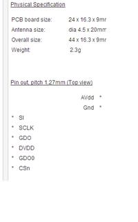
1. i have module which have the pinout as attached. there is no GDO1 and GDO2 pin. can you just tell me the which one is SO
2. different addition in address registers for different mode. can you explain this little.
3. to write some register value, i first have to send the addres and then the value on SPI.


1. Looks like the pin names are not copied correctly. There must be a pin SO/GDO1.

2. Everything is explained in the datasheet paragraph "10 4-wire Serial Configuration and Data Interface"
All transactions on the SPI interface start with a header byte containing a R/W¯ bit, a burst access bit (B), and a 6-bit address (A5 - A0).

3. Yes.
 

i got that SO pin.
i am trying to do this frm many days. learnt datasheet many times but i think i cant do it. no help from any side. no sample code from anywhere.

thanks for you kind help
 

Status
Not open for further replies.

Part and Inventory Search

Welcome to EDABoard.com

Sponsor

Back
Top