Continue to Site

Welcome to EDAboard.com

Welcome to our site! EDAboard.com is an international Electronics Discussion Forum focused on EDA software, circuits, schematics, books, theory, papers, asic, pld, 8051, DSP, Network, RF, Analog Design, PCB, Service Manuals... and a whole lot more! To participate you need to register. Registration is free. Click here to register now.

PCB layout design for pic programmer

Status
Not open for further replies.

Solar000

Member level 2
Joined
Feb 6, 2013
Messages
49
Helped
1
Reputation
2
Reaction score
1
Trophy points
1,288
Location
Greece
Activity points
1,649
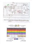
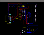
Hello, i want to make the pcb layout from a schematic i have for pic 16f877a programmer.I don't have much experience with pcb design,but
i made this layout and i want to tell me if this is correct or suggest a better solution.
I attach the schematic and what i made so far for the layout.
Thanks.
 

Attachments

  • LastScan.jpg
    LastScan.jpg
    1.3 MB · Views: 129
  • pcb layout.png
    pcb layout.png
    34.7 KB · Views: 127

there is nothing wrong, i can sea in ur pcb...
it depends on how you process pcb...if it is by simple method it will be defficult.. for that u need to increase the line width, min. distance betn. line pad, pad length and width .also use single side..
 

..... .also use single side..

I also wanted to ask this.Can it be done with one layer? I had difficulties connecting max232, pic and rs232 with one layer because of the lines.
For example,at max232 1 and 3 connect to a cap and 2 to another cap with ground.How it can be done with one layer?
 

You could do it in a single with, with probably just a few jumpers. You need to lay it out yourself... My experience is that for single sided board, a human can do a better layout then an auto-router. In particular:

"“Snake” your tracks around the board, don’t just go “point to point”. Point to point tracking may look
more efficient to a beginner at first, but there are a few reasons you shouldn’t use it. The first is that
it’s ugly, always an important factor in PCB design! The second is that it is not very space efficient
when you want to run more tracks on other layers." --- this was the most important piece of advise I learned from reading the following very good tutorial:
https://server.ibfriedrich.com/wiki/ibfwikien/images/d/da/PCB_Layout_Tutorial_e.pdf
 

Hi, I would like to suggest you some points about your PCB.

1- Try to avoid 90 deg corners in your tracks
2- If possible, make your design single sided
3- Try to use a power plane for your ground, it will save you many connections.
4- Also, why you use PIC16F877A?

- - - Updated - - -

Ohh, sorry I forgot to ask you. Are you using a socket for PIC16F877A?

I'm working in a PCB for you and need more info about your design. Can you tell me if you plan to use a socket for pic?
 

Hi,yes i will use socket for pic and for max.
I won't use rs232 jack because i will connect it with another circuit.This is the half.
Also all ports of pic to sockets for l293d 16pin like max.
Thanks for helping.
 

Yosmany325 ,it would be very helpful if you can give me an example of power plane for ground.You do the same for +5V?
Also if you can,the connection between pic and max with one layer,so i can learn to do the same for the rest circuit.
I can upload the above pcb file i made with altium, if you like.
The other circuit is bluetooth(lmx9838) to serial converter,but i downloaded the pcb files(https://www.ti.com/tool/lmx9838-sw) and it's ready i think.
The only modification is that i will connect the lines of two rs232 signals directly (without rs232jack).Also i will use a step up voltage to 12V for master clear to program in high voltage mode.The bluetooth works with 3.3V(or maybe 5V).
 

Hi Solar000, here is the pcb as I would design it. With respect to your last comment, I can't understand what do you want to do. I currently don't have Altium installed, so this design was made using Proteus. See the attached PDF file. Yosmany325.
 

Attachments

  • answer.pdf
    105.9 KB · Views: 115
Thanks Yosmany.Can you send me the pcb file you made with Proteus?I have it too.
I think its better with a jumper rather than wire.
Also why you have jump wire under the pic in your design and not connect the lines?There isn't something between.
 

The jumper below the socket of the PIC is here because if you draw it as a track the ground plane is broken.
 

Attachments

  • picprog_proteus.zip
    26.8 KB · Views: 150
Hi again Yosmany.I was studying your layout,looks very nice.
I have a question.How can you connect the other pins of pic the way it is now?It doesn't have much space.I want to connect the ports of pic to
7 sockets for l293d.I added to your schematic the l293 to show you,like the one on the top of the pic,with socket for output.
Also i added a res and a led to the dc regulator.
 

Attachments

  • picprog3.rar
    20.4 KB · Views: 92

Solar000 why do you left disconnected the ENA input of L293D chip?
 

Solar000 why do you left disconnected the ENA input of L293D chip?

I fully connected the top chip.The one at the top(U6).The others are connected the same way.I only connected the inputs to pic from the others.All EN to 5V.Vss 5V and Vs it's the motor voltage (9V depending on the motor).
Do you want me to connect all the others and send you?
 

No, is only for verification, I can connect it.
 

Ok i connected all L293d.For Vs i connected to 9V from the regulator at start(J2).My main power source will be 9V from J2 with adaptor or 9v battery
 

Attachments

  • picprog3.rar
    21.9 KB · Views: 83

Also, whay is the package of L293D you are using? DIP16 or SO20?
 

yes I saw this. Also I recommend you to use bypass capacitors on all L293D Vss and Vs. Search for more info with respect to this. The problem could arise when you start to switch on/off the L293 chips, as they will consume a lot of current from your circuit. Also there should be a way to sink out all the heat that will be generated. Do you plan to use this circuit to drive stepper motors? Why there are so many drivers?
 

I plan to use it to drive stepper motors or electromagnets.I need at least 6 drivers if not 7.
If you think you can add bypass capacitors to chip L293 chips.I am not sure what they do.Remember that Vss needs 5V and Vs the motor voltage 9-12V.
As for the heat,what can be done?I know that with 2 chips its not much heat.The motors don't consume so much.If there are 7 maybe.
 

With respect to heat one possible solution is to use heatsinks or make the copper area below the chip as large as posible, for example using a power plane. Also another solution, (more costly) is to use forced air flow, i.e. fans. I'll try to make a pcb for you but right now I don't have too much time. Yosmany325. If you can take a look to L293D datasheet.
 

Status
Not open for further replies.

Similar threads

Part and Inventory Search

Welcome to EDABoard.com

Sponsor

Back
Top