Continue to Site

Welcome to EDAboard.com

Welcome to our site! EDAboard.com is an international Electronics Discussion Forum focused on EDA software, circuits, schematics, books, theory, papers, asic, pld, 8051, DSP, Network, RF, Analog Design, PCB, Service Manuals... and a whole lot more! To participate you need to register. Registration is free. Click here to register now.

[51] lcd is working in proteus but not working in hardware, UC is AT89c51

Status
Not open for further replies.

Er_pank

Newbie level 4
Joined
Oct 22, 2013
Messages
5
Helped
0
Reputation
0
Reaction score
0
Trophy points
1
Activity points
47
lcd JHD 162A is working in proteus but not working in hardware, we are using Atmel AT89C51 microcontroller. The display occurs momentarily sometimes(rarely 1 or 2 times) but again the LCD turns back into showing bars. We've tried several methods like using simple programs for displaying "Hello" , "WALLE" etc. But again the same problem.

Here's the code for displaying "WALLE"

Code:
#include<regx51.h>
#define RS P1_7
#define RW P1_6
#define EN P1_5
#define DATA P2

void delay(int n);
void ins(void);
void dat(void);
void latch(void);

void main(void)
{
		   	
	 int k=0;
	 char x[6]="WALLE";


             delay(100000);
             ins();
             DATA=0X38; //8-bit Databus, Set 2 lines, and Select font size 5x7
             latch();
             DATA=0X0F;// It will display the characters, will display the cursor and it will blink.
             latch();
             DATA=0X10; // Set cursor on line 1. Use 0xC0 to write on line 2.
             latch();
             DATA=0X0; //Before changing to write data select. Make port 2 =0x0 so that LCD receives nothing
			 dat();
			 latch();
             for(k=0;k<=5;k++)
             {
                         DATA=x[k];
                         latch();
             }
			 while(1);


}

void delay(int n)
{
 int i=0,j=0;
 for(i=0;i<=n;i++)
 for(j=0;j<=10;j++);
}

void ins(void) //Instruction select routine
{
             RS=0;
             RW=0;
}
void dat(void) // Data select routine
{
            RS=1;
            RW=0;
}
void latch(void) // Latch routine
{
            EN=1;
            delay(1000);
            EN=0;
            delay(1000);
}

Diagram is given here:


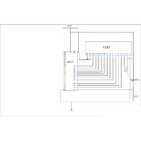
https://obrazki.elektroda.pl/1332797100_1382441491.gif
 
Last edited by a moderator:


Code C - [expand]
1
2
3
4
5
6
7
8
9
10
11
12
13
14
15
16
17
18
19
ins();
DATA=0X38; //8-bit Databus, Set 2 lines, and Select font size 5x7
latch();
ins();
DATA=0X0F;// It will display the characters, will display the cursor and it will blink.
latch();
ins();
DATA=0X10; // Set cursor on line 1. Use 0xC0 to write on line 2.
latch();
ins();
DATA=0X0; //Before changing to write data select. Make port 2 =0x0 so that LCD receives nothing
latch();
 
for(k=0;k<=5;k++)
{
dat();
DATA=x[k];
latch();
}

 
Last edited:

i think your circuit diagram is wrong . because JHD 162A has pin no. 4 , 5 , 6 is RS , RE , E is connected to the micro-controller pin no 10,11 and 16 which is PORT3 of 89c51 and in your code u mentioned port 1 something wrong or not?
 

Yes. pin connections are wrong. Have to put a resistor on pin 15 or 16.


Code C - [expand]
1
2
3
#define RS P3_0
#define RW P3_1
#define EN P3_6


It should be like this:

LCD_8051_ckt.JPG
 

Thanks for your suggestion, will implement it.

what might be the proper time delay for this uC, and how to calculate the time delay ?
 

Status
Not open for further replies.

Part and Inventory Search

Welcome to EDABoard.com

Sponsor

Back
Top