Continue to Site

Welcome to EDAboard.com

Welcome to our site! EDAboard.com is an international Electronics Discussion Forum focused on EDA software, circuits, schematics, books, theory, papers, asic, pld, 8051, DSP, Network, RF, Analog Design, PCB, Service Manuals... and a whole lot more! To participate you need to register. Registration is free. Click here to register now.

Solar Circuit Help Please

Status
Not open for further replies.

zartoop

Newbie level 3
Joined
Jun 3, 2012
Messages
4
Helped
0
Reputation
0
Reaction score
0
Trophy points
1,281
Activity points
1,325
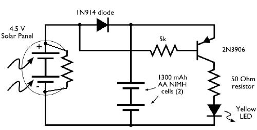
I have built the circuit below but cannot get the led to light at all. The circuit is meant to to detect light and dark (via the solar cell) and turn on the led when it is dark. Also the solar panel is meant to charge the battery. The circuit is from Evil Mad Scientist.

I have used a PN200 transistor and breadboarded it. Checked and double checked everything but for the life of me can't get it to work. Please help.

Can someone please explain the details of operation for me?

Thank you for helping a dummy.

2963306745_82a5b69db1_o.jpg
 

If the AA cells give a voltage below 2V if not fully charged, you will have a problem turning on the LED. Make sure that the LED still comes on if you short out the collector and emitter of your transistor. You will lose an additional 0.2V or so over the transistor itself.
 

    V

    Points: 2
    Helpful Answer Positive Rating
If white led used then it requires 3 cells. Check led with 50 ohm resistor sepeately if it glows with battery and solar panel.
 
  • Like
Reactions: IanP

    IanP

    Points: 2
    Helpful Answer Positive Rating
The correct operation of this circuit relays on propers selection of solar panel, battery and LED.
And it works like this:
When there is no voltage generated by the solar panel, or the voltage across the panel is U[battery]-0.7V, the Base voltage of the PNP transistor will be 0.7V below the Emitter voltage and the transistor will be switched on – LED-on.
When the panel generates voltage above the U[battery]+V[diode] there is some current flowing from panel through diode to the battery. In the same time the Base voltage of the PNP is above the Emitter voltage and the PNP is off – LED-off.

Now, as E-Design mentioned, the battery voltage has to be higher then the LED voltage plus some voltage across the PNP.
2xAA rechargeable NiCad (or Ni-MH) could be not enough – roughly 2.4V.
I would try 3xAA – 3.6V. In this case the solar panel has to generate more than 3.6V(bat)+0.7(diode) 4.3V
Also try to use an LED with the lowest voltage, then all what you need to do is to select a resistor to limit the LED’s current ..

:wink:
IanP
 
  • Like
Reactions: DrWhoF

    DrWhoF

    Points: 2
    Helpful Answer Positive Rating
Use a Red or Green LED. Yellow/ white/ blue have a higher knee voltage and might not work.
 
  • Like
Reactions: DrWhoF

    DrWhoF

    Points: 2
    Helpful Answer Positive Rating
To check this circuit give 6V for battery and vary the solar cell voltage from 0 to 8 and check the results........ Put 1k on base and 330 ohm on collector........
 
  • Like
Reactions: DrWhoF

    DrWhoF

    Points: 2
    Helpful Answer Positive Rating
Thanks to everyone for your help. Now I understand and got it to work!

- - - Updated - - -

When there is no voltage generated by the solar panel, or the voltage across the panel is U[battery]-0.7V, the Base voltage of the PNP transistor will be 0.7V below the Emitter voltage and the transistor will be switched on – LED-on.
IanP

Ian - I don't understand how the base voltage is 0.7v below the emitter. The diode has a voltage drop of 0.7v but only when forward biased. In the condition where the panel is not conducting or disconnected the base is 'floating' ?
 

Zartoop is right, in the dark, a PV panel is virtually open circuit so no base current can flow. It should really have a bias resistor between the transistor base and the negative line.

Brian.
 

  • Like
Reactions: DrWhoF

    DrWhoF

    Points: 2
    Helpful Answer Positive Rating
I just checked a small '4.5V' PV panel dark leakage current with 4.5V across it and it indicates a resistance >6M Ohms. That isn't enough to bias a 2N3906 to saturation, especially when you consider the leakage current through the diode as well.

If we assume some assumptions:
1. together the two NiMH cells produce (2 x 1.2V) = 2.4V
2. the LED Vf is 2.0
3. the transisor VCEsat is zero (I know it never will be)
4. the 2N3906 has a Hfe of 200 (mid range value @ 10mA from Fairchild data sheet)

Then the LED can conduct at most (batteries - Vf)/50 A = 8mA
The base current must be more than Ic/Hfe = 40uA

So the minimum leakage resistance (ignoring the 5K resistor) has to be (2.4V - Vbe)/40uA = 45K Ohms.

That means unless there is a very leaky PV panel it will not provide enough bias current. I would shunt it with a resistor, say 39K or less. The effect on charging current would be negligible but it would ensure the LED lights when it's dark.

Brian.
 
Use a Red or Green LED. Yellow/ white/ blue have a higher knee voltage and might not work.
A dim OLD green LED had a forward voltage a little higher than a red LED.
But a very bright MODERN green LED has a forward voltage exactly the same as a white or blue LED.
 

Status
Not open for further replies.

Similar threads

Part and Inventory Search

Welcome to EDABoard.com

Sponsor

Back
Top