Continue to Site

Welcome to EDAboard.com

Welcome to our site! EDAboard.com is an international Electronics Discussion Forum focused on EDA software, circuits, schematics, books, theory, papers, asic, pld, 8051, DSP, Network, RF, Analog Design, PCB, Service Manuals... and a whole lot more! To participate you need to register. Registration is free. Click here to register now.

Why SSD is not working with ULN2803?

Status
Not open for further replies.
Joined
Dec 4, 2012
Messages
4,280
Helped
822
Reputation
1,654
Reaction score
791
Trophy points
1,393
Location
Bangalore, India
Activity points
0
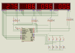
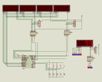
Why SSD is not working with ULN2803? I have attached the .hex file and Proteus file. The NOT gate version works fine but ULN version doesn't work. .hex file is same for both simulations. CA type display are used. There are 4 rows and 3 columns of SSDs. I need to display 4 integers which can vary from 0 to 999.
 

Attachments

  • 4X3SSD.rar
    39.8 KB · Views: 89

Schematic attached. Only one SSD is ON at a time. Each SSD contains 7 segments + dp. SSD is 7 inch type. Each segment of one SSD has Serias - Parallel combination of LEDs. The Series line has 7 LEDs and there are 2 parallel lines. So 20 mA for one series line and 40 mA for 1 segment. approx value of current is 40 * 8 mA = 320 mA for one SSD. CA pin has to provide max 320 mA. I am using ULN for enabling/disabling SSDs.

As only one segment is ON at a time. uC data bus to SSD is enough to sink current from cathodes of LEDs. Ofcourse it might need resistors. I haven't calculated it completely.

97347d1381937973-not.png


97348d1381937974-uln.png
 

Attachments

  • NOT.png
    NOT.png
    50.6 KB · Views: 125
  • ULN.png
    ULN.png
    45.7 KB · Views: 127
Last edited:
i tried and get something wrong with uln2803 i test all the way but i am failed . and last i remove one by one part and replacing uln2803 with hcf40106 result got fine . so i tried again and inform u.
 

Hi ULN is a open collector configuration you can use it only for CC configuration.. If you put a pull up you can use it for CA...

- - - Updated - - -

The pull up values shd be enough low to drive the segments and I found that ON time of segments 2,3, &4 are low comparing to 1 so the first one works with ULN itself....
you cant see any thing in the display because there is no case called dim in the prorteus only ON and OFF....
untitled1.JPG
 

Isn't there pullups in my schematic?

As I mentioned max current for one segment of each SSD (digit) is 40 mA but I run at 20 mA, so I am working at half max current of SSD. Max current is 320 mA and I run at 160 mA. PWR supply for SSD is 12V.
600 Ohms resistance is needed on multiplexed data lines. I am using 570 ohms. pullup can be 36 ohms.
 
Last edited:

@nick703

40106 is Hex Inverter. What is special about it. My NOT gate version works in simulation but not gate cannot source 320 mA. I even tried PNP (TIP30 1A max current) transistors instead of ULN but it doesn't work too.

- - - Updated - - -

Can you tell which lines of the circuit you have connected to Oscilloscope?


Is the ULNs switching speed slow?


4 rows and 3 columns are used.

switching sequence is like this

col row

0 0
0 1
0 2
0 3

1 0
1 1
1 2
1 3

2 0
2 1
2 2
2 3
 
Last edited:

Hi connect like this, The 1st SSD glowing for me with ULN..... but the ON time is found to be low for others.....
untitled2.JPG
 

Status
Not open for further replies.

Part and Inventory Search

Welcome to EDABoard.com

Sponsor

Back
Top