Plecto
Full Member level 5
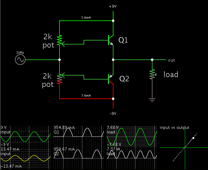
Hi. I've been messing around with class AB output stages and their biasing. The first schematic I looked at was this one:
**broken link removed**
I thought it was a great way to bias a class AB stage, but when looking at the output current of the op-amp (which I use as a input stage) as well as the output voltage capabilities, I wasn't as happy anymore. To increase the bias current, R1 and R2 have to be lower in value, but lowering them too much will quickly exceed the current capabilities of the op-amp. By having a low bias current and high R1 and R2 values, the output peak voltage will be lowered. I made this formula to calculate output peak voltage vs. R1 and R2 values: VRL=(Hfe*RL(10Vs-7))/(10(Hfe*RL+Rb)), where VRL is the load voltage, RL is the load resistance and Rb is the biasing resistor values. Using darlington pair won't help at all if my calculations are correct.
I thought about using mosfets instead (despite the negative opinions people have towards fets in audio applications) and this will remove the issue as no current flows into the gate. This means that the bias current can be set with high value resistors without limiting the output voltage, but I would instead have to deal with the threshold voltage (which is often around 4V perhaps?) which will limit the output voltage instead.
I then thought of replacing the diodes with resistors, doing this seems to be better solution, but I'm not sure if there's any drawbacks of using resistors instead of diodes with biasing a class AB stage that I'm not seeing?
I'm wondering if there are better ways of doing this. I would really like to have as high efficiency as possible without having to resort to more powerful input stages