Continue to Site

Welcome to EDAboard.com

Welcome to our site! EDAboard.com is an international Electronics Discussion Forum focused on EDA software, circuits, schematics, books, theory, papers, asic, pld, 8051, DSP, Network, RF, Analog Design, PCB, Service Manuals... and a whole lot more! To participate you need to register. Registration is free. Click here to register now.

[SOLVED] closed loop dc motor control using current !??

Status
Not open for further replies.

Electro nS

Full Member level 6
Joined
Mar 9, 2013
Messages
324
Helped
49
Reputation
98
Reaction score
48
Trophy points
1,308
Activity points
3,818
hello guys

i want to control the speed of brushed dc motor in a closed loop mode (12v 300W dc motor) . i am using H bridge for bidirectional operation . and i have implemented current sensors for protection.

I CANNOT install encoders to the motors , very difficult mechanically . I Am trying to escape from back emf measurment , they say its complex electronically . (extra harware , noise ....)

I have read somewhere

https://prezi.com/ch0a650pnbkf/speed-control-of-h-bridge-controlled-dc-motors/

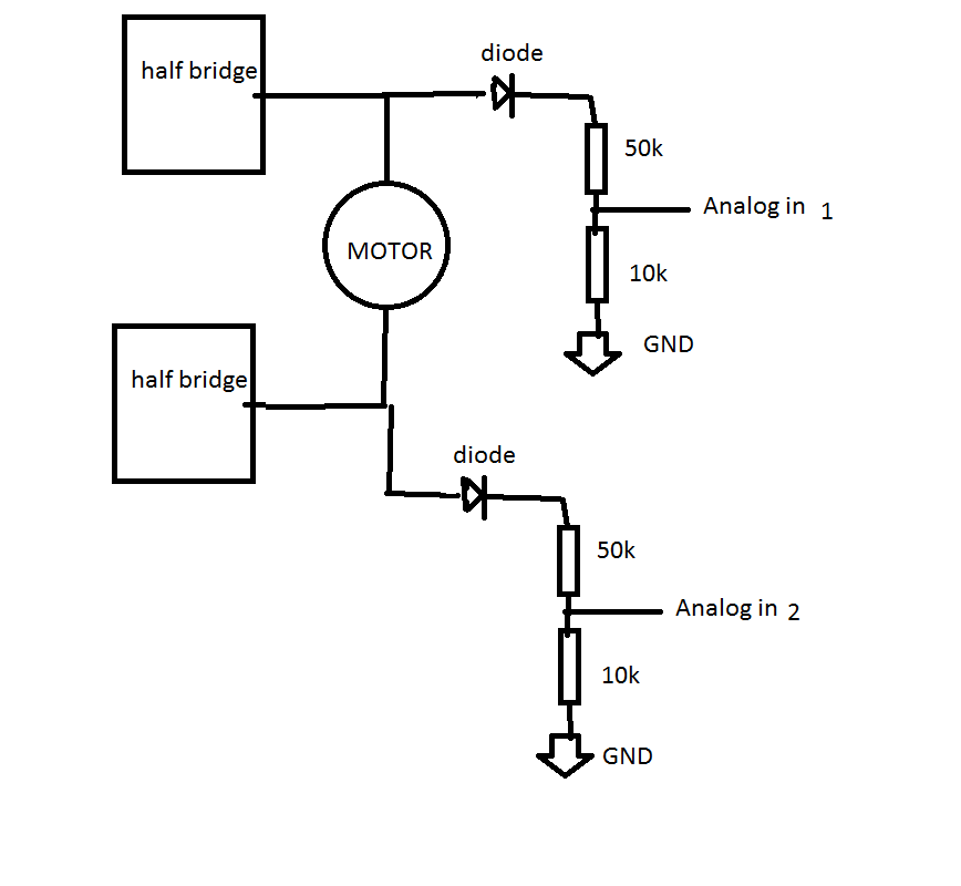
https://obrazki.elektroda.pl/1018953600_1381759337.png

that you can use current to measure speed ( even if not presice , its OK ) that would be great since the sensors are already implemented and no hardware change is needed
but cannot understand how does that work , isn't current related to torque not speed ??

please help . any information would be appreaciated
 

As explained in the second link, you can estimate speed based on motor voltage and current, assuming a linear speed drop versus load torque respectively current. It's less accurate than an external speed sensor.

For a H-bridge operated motor, you need to additional measure motor voltage.
 
As FvM mentions, it can be determined, but you require to determine the kw constant and the Rs. And to be able to measure the actual applied voltage at the motor terminals, as both the H-bridge and the current-sensing resistor will have some voltage loss.

You don't mention how large your motor is. In larger motors, Rs is quite small, and you'll require a 4-wire resistance measurement to determine it accurately.

The kw constant, unless you can get it from the manufacturer, you will require to rotate the motor at a precisely known speed, and measure the open circuit terminal voltage.
 
The motor emf is directly proportional to speed, but this is different from the applied voltage due to the winding current and the winding resistance. Vemf is not directly observable, but by measuring the applied voltage and current, and knowing resistance, you can derive Vemf with improved accuracy.
 
For a H-bridge operated motor, you need to additional measure motor voltage.

how am i supposed to measure the motor voltage , in both directions ?? can you clarify a bit (should i enter both motor terminals to a OP amp or something ???)

- - - Updated - - -

As FvM mentions, it can be determined, but you require to determine the kw constant and the Rs. And to be able to measure the actual applied voltage at the motor terminals, as both the H-bridge and the current-sensing resistor will have some voltage loss.


You don't mention how large your motor is. In larger motors, Rs is quite small, and you'll require a 4-wire resistance measurement to determine it accurately.

The kw constant, unless you can get it from the manufacturer, you will require to rotate the motor at a precisely known speed, and measure the open circuit terminal voltage.

first i told you there is no current sense resistor , i am using a hall effect current sensor.
second i mentioned how large the motor is 12v 300w iin my first post .
third do you think i i use 2 motors of the same kind and attach the output shaft to each other and give one of them voltage and read output voltage of teh second . and i already have a stroboscope , would this give me Kw ???
 

Using a differential amplifier with a LPF is one simple way, yes.


Indeed, I missed the 300watt, 12 volt paragraph.
Rs is not the current sense resistor, but the motor's series equivalent resistance.
Your idea to define Kw is a good one.
 

The differential amplifier you sent should measure across motor terminals.
Note that common mode rejection ratio of the circuit will be critical to sense motor voltage properly --> Use matched precision resistors (0.1%) for the amplifier circuit as well as low tolerance stable capacitors C0G / NP0.
 
Note that common mode rejection ratio of the circuit will be critical to sense motor voltage properly

for noise purposes ???

and another question does the rail to rail voltage of the amplifier should be higher than the motor voltage ?? example if motor is 24v , can a +5/-5 or +5/GND OPAMP work ??
as i recall from electronics the maximuim output of the OPAMP is Vrail+ and Vrail- . please explain .
 

You have 2 options:
Either use an opamp which can be supplied by 30 volts or use a voltage divider from the motor terminals to use a lower rated amp.

- - - Updated - - -

There are some "over the top" amps from Linear Tech which may also work....
 
i thought of a simpler solution that uses 2 analog inputs to sense the motor voltage on both directions. use analog 1 if motor is CW (at this time the second side of the motor is at GND) and vis versa for CCW

here is the block diagram , do you think guys ,would it work ??? how does this method compare to the opamp ?? (noise ?? precision ?? something else ??)

link :
 

Status
Not open for further replies.

Similar threads

Part and Inventory Search

Welcome to EDABoard.com

Sponsor

Back
Top