Continue to Site

Welcome to EDAboard.com

Welcome to our site! EDAboard.com is an international Electronics Discussion Forum focused on EDA software, circuits, schematics, books, theory, papers, asic, pld, 8051, DSP, Network, RF, Analog Design, PCB, Service Manuals... and a whole lot more! To participate you need to register. Registration is free. Click here to register now.

[SOLVED] Help to tidy up Mono Synth Front end

Status
Not open for further replies.

Now_and_Zen

Newbie level 5
Joined
Oct 1, 2013
Messages
10
Helped
1
Reputation
2
Reaction score
1
Trophy points
3
Activity points
91
Hi Everyone,

My first post, so do be gentle with me ;-)

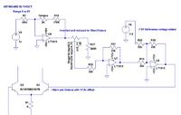
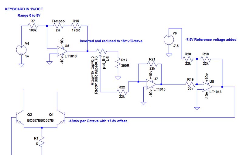
Here's my schematic:


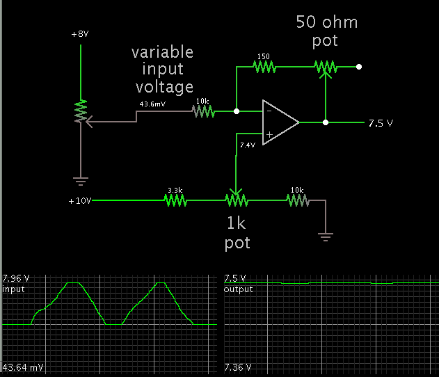
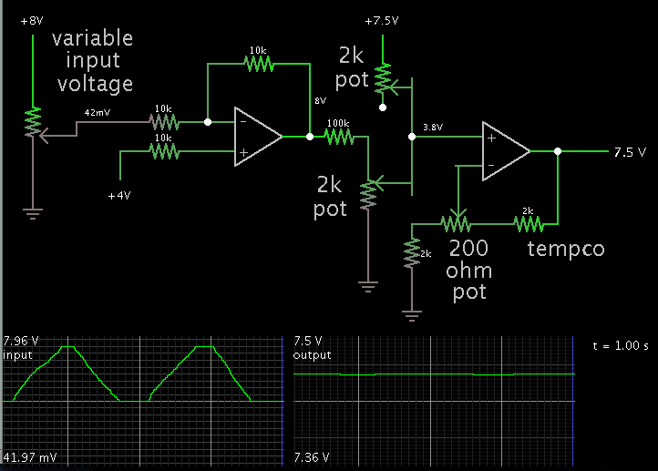
I am designing a vintage style analog monosynth which needs 1 volt per octave input from a Midi to CV convertor.

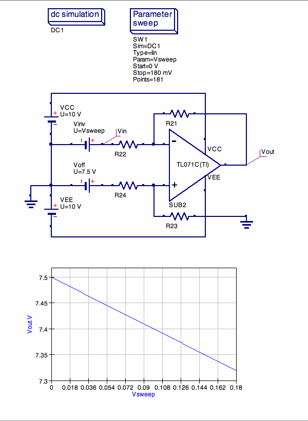
The base of one side of the pnp expo convertor requires -18mv per octave, which needs to be offset by +7.5 volts, so 0 volts input would give +7.5v, 1v in would give +7.482v, 2V in would give +7.464v etc to the base of Q1

The voltages need to be very precise for accurate tuning, hence the use of precision op amps.

I have got the desired result from the circuit shown, but it is messy and I'm sure it can be simplified; I've tried adding bias directly to the op amps but can't seem to make it work.

I was going to use a TL431 and associated resistors to generate the 7.5v reference voltage. I have + and - 10v rails and it can be taken from positive or negative rail. I've shown it taken from from negative rail and inverted.

I'm happy with the circuit up to the trim pot, its the ref voltage and two inverting op amps implementation that seems messy.

I'm a hobbyist, nothing pro here as you can probably tell!

Be really grateful if anyone could help.

Thanks,

Allan
 

It appears you want to input 0 to 8 V...

and convert it to a range of 7.5 to 7.356 (linear response).

According to this simulation, one op amp should do the job.


The scope traces portray the left-hand pot dialing up to 8V and back down to 0V. The resulting output volt levels are labelled at right.

I had to fine-adjust the gain (topmost pot), and the 7.5 (or 7.4) V reference (bottom pot).

You can use the TL431 as you stated, to provide 7.5 V at the non-inverting input.
 

Hi Brad,

Many thanks for the reply, it would be perfect except that I forgot to mention that it must have the 2K tempco resistor and 175R resistor in the feedback loop of the first op amp :oops:
They have a combined temperature coefficient of 3300ppm/degC which compensates for the -3300ppm/degC temperature drift in the (downstream) pnp current mirror exponential converter, without this the tuning of the current controlled oscillator drifts as the temperature rises.

So, this more or less determines the layout of the circuit up to the trim pot unless it is possible to add the offset voltage and keep the same stage gain. I did try to use a non inverting op amp stage after it instead of two inverting stages but couldn't seem top get it to work correctly.


Allan
 

Yes, my schematic tries to do too much in one stage. Two stages are probably necessary.

Suppose you start by inverting the 0-8V? So you get 8 to 0V out?

Then reduce it with a simple resistor divider.

Finally send it to another op amp which is configured as a summer. You add in the 7.5V through an equal input resistance.


I cannot say whether you would or wouldn't need the tempco resistor.
 

Looking better! There is still a possible issue to resolve though, as the 18mv per octave is approximate and needs to be set to give exactly 1 octave rise in oscillator pitch for 1 volt rise in keyboard control voltage, which is why there is a trimmer in the original schematic to give an adjustment range circa 16 to 20mv. Problem is, because we now have 7.5v ref going into summer stage we will be scaling that too as we adjust the trimmer pot. Really need the 7.5v to be fixed and not changed by adjustment of the control voltage trimmer.

The PTC tempco resistor is necessary, it is almost universally used in this kind of application. There are other ways of achieving the same result but this is the simplest and cheapest. The easily obtained values in through hole package are 1k and 2k. For anyone interested in further reading there is a very good explanation at https://www.schmitzbits.de/ under the sub heading "what is all this exp and tempco stuff". And a more mathematical explanation here **broken link removed**
 

... keep the same stage gain. I did try to use a non inverting op amp stage after it instead of two inverting stages but couldn't seem top get it to work correctly.

After the tap of your poti you could do it with one opAmp and 4 equal resistors (say: 100 kΩ) , and a positive reference voltage of 7.5V :
 

Hi eriki,

Many thanks for the schematic. No problem with using +7.5 ref voltage, however the signal from the first op amp is a negative falling slope. It starts at zero volts and falls at the rate of 20mv per 1V input. I think that this circuit assumes a positive going slope starting from zero volts and rising as it is an inverting stage?
 

Looking better! There is still a possible issue to resolve though, as the 18mv per octave is approximate and needs to be set to give exactly 1 octave rise in oscillator pitch for 1 volt rise in keyboard control voltage, which is why there is a trimmer in the original schematic to give an adjustment range circa 16 to 20mv. Problem is, because we now have 7.5v ref going into summer stage we will be scaling that too as we adjust the trimmer pot. Really need the 7.5v to be fixed and not changed by adjustment of the control voltage trimmer.

Yes, apparently another stage is needed to provide a separate input where you can add 7.5V alone.

It's starting to look as though I would end up with a duplicate of your topology.

I suppose you need to fit the entire range of your signal inside a few tenths of a volt...

in order to send the current through the exponential converter (PN junctions)...

which will output a voltage based on the diode curve?

(The diode curve is active over a range of a few tenths of a volt.)

Then apply it to a V-to-F converter? And the frequency will correspond exactly to the note you pressed?


Correct, it works in the narrow range where the transistor is a good exponential to linear convertor. Didn't know it was called the diode curve though... One of many huge gaps in my knowledge :)

The oscillator itself consists of a timing capacitor which is charged by an integrator up to a threshold level where a comparator fires a fet transistor which discharges the cap and the cycle is reset and starts over again; thus producing a sawtooth waveform. The expo transistor drains current from the timing capacitor, the faster the current is drained then the higher the oscillator frequency. So the oscillator core is actually a linear current controlled oscillator.

Thanks for all of the interest and help, my solution to this looked messy but seems it cannot be simplified much, if at all.

Allan
 

... however the signal from the first op amp is a negative falling slope. It starts at zero volts and falls at the rate of 20mv per 1V input. I think that this circuit assumes a positive going slope starting from zero volts and rising as it is an inverting stage?

True; I just was confused as the blue text for the input voltage didn't contain the minus sign, sorry! So we come back to a negative (-)7.5V offset voltage at the inverting input, and your -20mV/octave input voltage to the non-inverting input of my former circuit. Again, all 4 resistors have the same value (≦ 1% tolerance suggested):
non_inv_opAmp_w_offset.gif
 

True; I just was confused as the blue text for the input voltage didn't contain the minus sign, sorry! So we come back to a negative (-)7.5V offset voltage at the inverting input, and your -20mV/octave input voltage to the non-inverting input of my former circuit. Again, all 4 resistors have the same value (≦ 1% tolerance suggested):

Hi Erikl,

Great work! That configuration works perfectly in LT spice as it does in your sim. That has saved an op amp and a stage :grin:

Many thanks for solving the problem!

Allan
 

Status
Not open for further replies.

Similar threads

Part and Inventory Search

Welcome to EDABoard.com

Sponsor

Back
Top