Continue to Site

Welcome to EDAboard.com

Welcome to our site! EDAboard.com is an international Electronics Discussion Forum focused on EDA software, circuits, schematics, books, theory, papers, asic, pld, 8051, DSP, Network, RF, Analog Design, PCB, Service Manuals... and a whole lot more! To participate you need to register. Registration is free. Click here to register now.

[SOLVED] AC MEASUREMENTS USING CRO (Doubts about working of CRO)

Status
Not open for further replies.

myfaithnka

Advanced Member level 4
Joined
Nov 5, 2010
Messages
106
Helped
2
Reputation
4
Reaction score
2
Trophy points
1,298
Activity points
2,022
hi all,

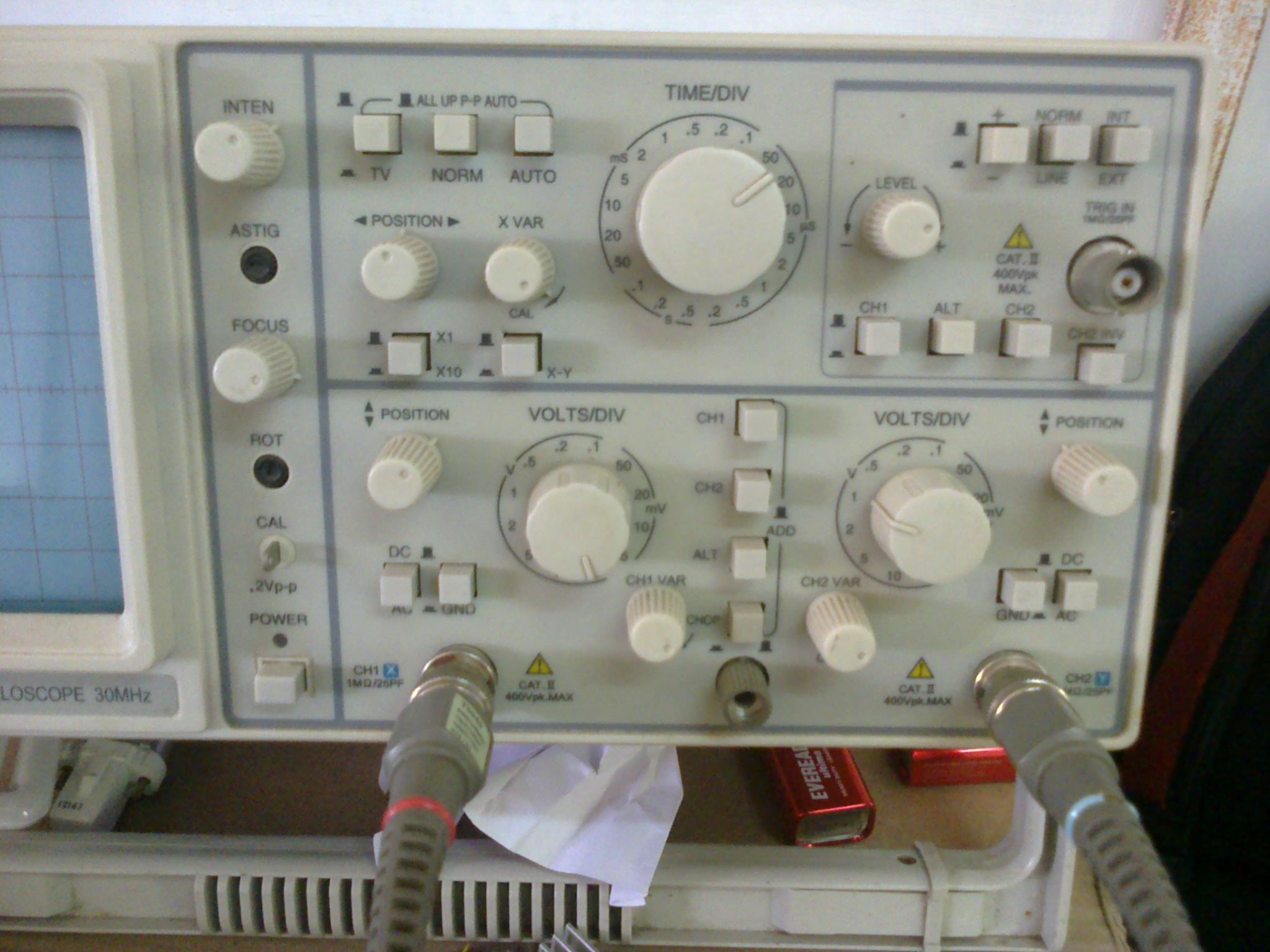
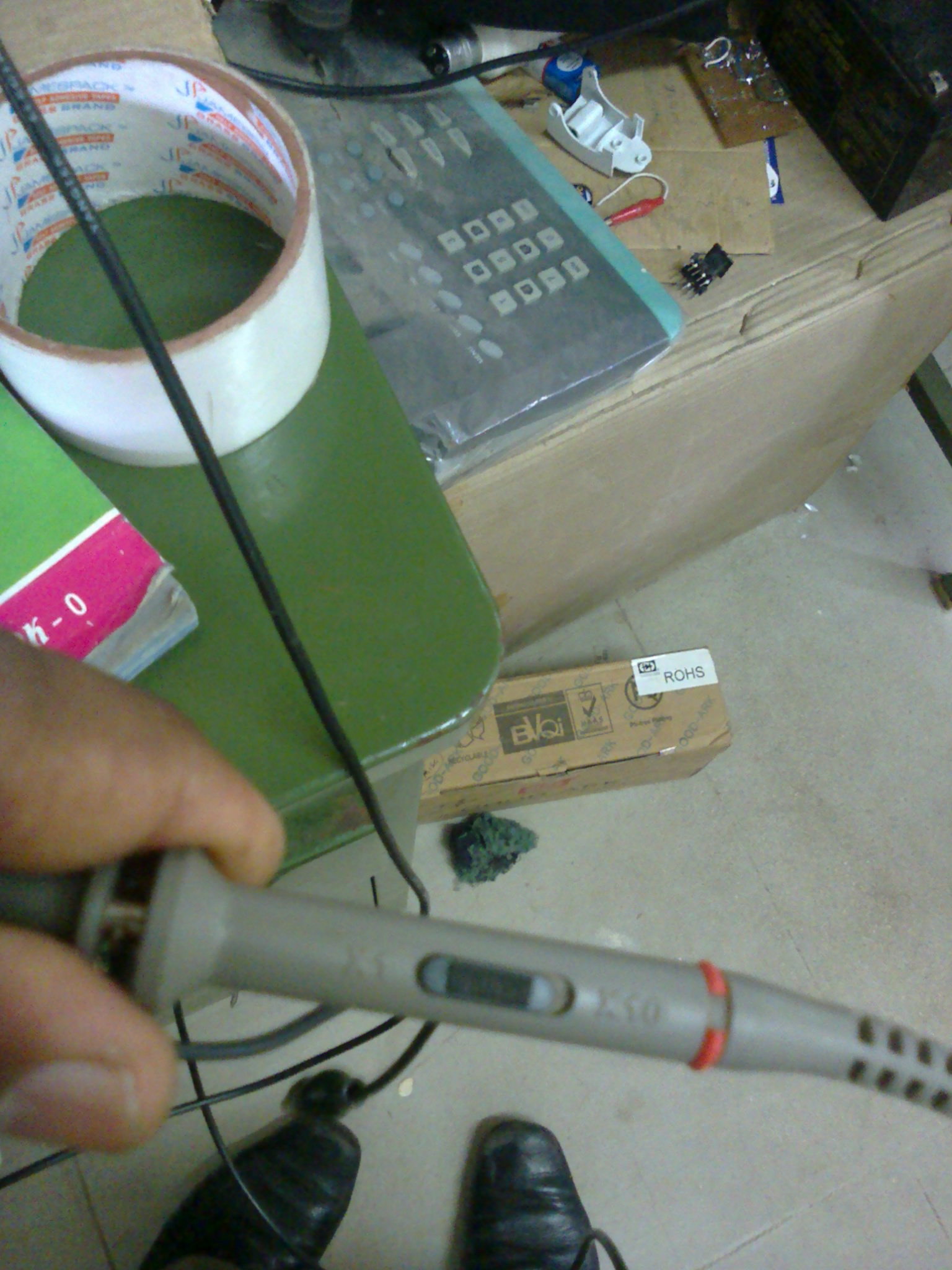
i am trying to see the waveforms of electronic ballast using a CRO.

the ELCB drips here,I am new to AC circuits working over mains.

What are the
PLEASE HELP.

thank you.
 

If CRO is the Cathode-Ray Oscilloscope, then today.s oscilloscopes use a different display. You can use any good oscilloscope to observe voltage waveforms. What exactly you need? Do you have some schematics and specifications?
 
If this is an electronic ballast in a mains florescent light, then the ballast will be connected to the mains. When you put your earth probe on the circuit, you are earthing the neutral of the mains causing excessive neutral current that trips the ELCB. Either run the ballast and kit from a mains isolating transformer, or use your CRO indifferential mode, connect the inputs via 10 :1 probes and view the difference between the two probe inputs. It is useful if both channels are set to the same volts/div. (makes the calculations easier.
Frank
 
Mains measurements are dangerous, especially for the inexperienced. 8-O I suggest you refrain from that or use an isolation transformer.
 
Differential measurement probes will be your best friend for working on mains-connected devices. I know they're expensive but they are simply awesome for viewing mains-connected wave-forms on an earth-grounded scope.
 
Hi all,

jiripolivka,
i am trying to understand a normal electronic ballast the figure of the ballast is like this,
**broken link removed**

chuckey,
I am having a CRO, posting the photos here.


I think its because of the earth leakage,so in difference mode I am doing as follows,
i am connecting the probes' ground to electrical ground.
Then the one probe to the dc negetive line and another to the trasistors collector to view the transistor switching chara.
The difference mode should be the chop button in my CRO(am i right? :( )
I have to use the X10 button and the probes should be in x10 mode.
is the coupling in ground mode ?
I am total noob in Mains circuits.

thanks,
good to see you again :)

crutschow,
I dont have isolation transformer,pls help me with any possible alternate methods.

GeorgesWelding,
I have 2 probes supporting both x1 and x10 modes. pls help.

thanks and regards,
nithin
 

When you are measuring the waveform of a directly connected mains-connected device you cannot connect the ground clip of the probe to any point other than EARTH ground. If you do you will create a low resistance path to EARTH and you will at the very least melt the ground lead of your probe but you may damage your scope. I build switch-mode power supplies so this became a huge issue for me to view the switching wave-forms because the switching IGBTs are directly connected to the rectified mains voltage. A differential probe solves all those issues. The probe has an amplifier box that connects to a single channel of your o-scope then on the other side of the box is a positive and negative lead. Either of these leads can be connected to points above or below EARTH ground and the scope will display the difference in voltage between the two leads. It is basically just a difference amplifier. You can build one yourself but the bandwidth and Common-Mode Rejection Ratio wont be nearly as good as what you can get out of a real one.

Here is a link to one of the cheaper ones I found: https://www.interworldna.com/pico/active_differential_probes.php#ta041
Model #: TA041. Measures up to 25MHz and +/- 700V and has an input impedance of 4M-Ohm/5.5pF

If you wish to build one yourself, here is a link to the thread I started about the one I designed myself using a simple TL074 Quad Op-Amp: https://www.edaboard.com/threads/299513/
Like I said though, if you build this one, the bandwidth isn't that great. The on-time delay is around 50ns and the rise-time is around 200ns. Off-time delay/fall-time is pretty much the same as the on/rise. So 100KHz is about the fastest you can read with my home-brew device before the rise/fall-times start to become a real issue. I'm working on improving my design using an op-amp with a much-much-MUCH higher slew-rate but I'm getting some ringing in the circuitry that I can't get rid of so once I figure that issue out my device should be able to work up to 1Mhz. The input to my difference amplifier is provided with 2 X10 probes, the probe's internals are shown in the schematic in the last post, but the amplifier gives an attenuation of X100 with the X10 probes. Input impedance is 9.1M-Ohm.
 
The advice to use an isolation transformer is best to follow. Then the bottom line of the schematic (or any point in it) can be connected to the common ground with the oscilloscope probe. Be ready to see overshoots and use probes that can measure >1 kV peak.
 
Status
Not open for further replies.

Similar threads

Part and Inventory Search

Welcome to EDABoard.com

Sponsor

Back
Top