jbeniston
Advanced Member level 1
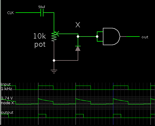
Does anyone have any recommendations for a low-power pulse shortening circuit?
i.e. I have an incoming clock pulse and I would like to reduce the duty cycle by a rough amount.
i.e. I have an incoming clock pulse and I would like to reduce the duty cycle by a rough amount.
") )
)