pasindua
Newbie level 3
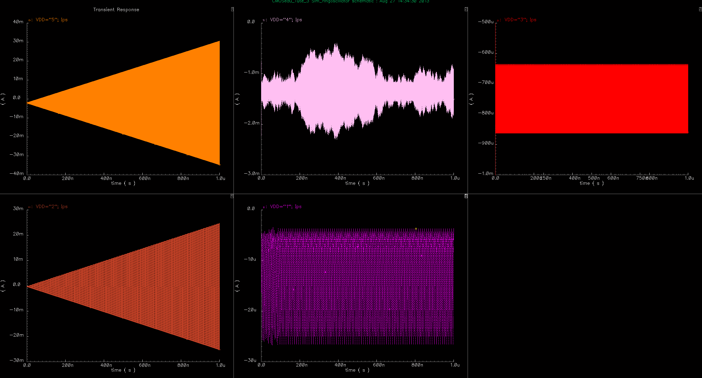
I am working on designing a simple ring oscillator circuit in Cadence ICFB 5.141. I have designed a ring oscillator schematic with 15 inverters from NCSU_TechLib_ami06 library (0.6 um, 5 V). I performed a parametric sweep of power supply voltage (VDD) from 1 V to 5 V, while running 1 us transient simulations of the schematic design.
From the results of the simulation, I noticed that the power supply currents' (Ips) magnitudes for VDD=1 V,3 V, and 4 V are stable. However, for VDD=2 V and 5 V, Ips magnitude increases with time. For example, at VDD=2 V, magnitude of Ips increased from 100 uA to 24 mA along the 1 us simulation duration.
I am at a loss on how to explain this. First I suspected that may be the ring oscillator frequency is not stable and increases with time, causing Ips magnitude to increase. However, it seems that the oscillation frequency is stable. Can anyone help me to understand why this is happening?
Thanks in advance!