Continue to Site

Welcome to EDAboard.com

Welcome to our site! EDAboard.com is an international Electronics Discussion Forum focused on EDA software, circuits, schematics, books, theory, papers, asic, pld, 8051, DSP, Network, RF, Analog Design, PCB, Service Manuals... and a whole lot more! To participate you need to register. Registration is free. Click here to register now.

full bridge with ir2110 problem

Status
Not open for further replies.

nxhnam

Newbie level 3
Joined
Aug 20, 2013
Messages
3
Helped
0
Reputation
0
Reaction score
0
Trophy points
1
Activity points
29
Hi,
Sorry for my bad English.
I'm making a full bridge circuit with ir2110 . i use 4 isolated power 5v , 12v(1), 12v(2), 12v(3). The reason is I use power supply for Vb and Vs pin instead of bootstrap .
When I test my circuit in PCB , i provide all 5v and 12V power to driver IC , and there is no problem, but when I continue connect 24V (i do not put the load ) , the right driver is hot , and it died lowside (pin 1 2 3 ), the highside mosfet in right zone is hot but it is not die. The right fuse is break. Then , I put driver one by one (I do not put 2 driver in PCB together) and provide all 12V 5 V 24V , there is no problem .In all case , I dont put HIN , LIN signal to driver .
I hope some help from you
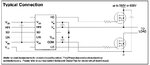
This is my schematic .
Thank you.
Hbridge.JPG
 
Last edited:

If there is no load there is no difference between the left and right drivers Dont put the Hin and Lin in open one shd be atleast any one of it should be grounded better you ground both of them and check for proper operation.. I think you know if you give high ti both the pins It could damage the fuse....
 
  • Like
Reactions: nxhnam

    nxhnam

    Points: 2
    Helpful Answer Positive Rating
But it is not mentioned in its application note...
Not particularly. But what do you conclude from this fact?

Looking into the details, there's a logic supply offset voltage specification in the datasheet. Obviously, IR2110 has been designed with separate grounds to tolerate a certain ground shift between control and power circuit. As the datasheet clarifies, there's a level shift circuit to bridge the ground shift.

But what happens if you use floating supplies without a ground connection? How can you keep the maximum logic offset voltage specification? Unfortunately you can't.
 

But what happens if you use floating supplies without a ground connection? How can you keep the maximum logic offset voltage specification? Unfortunately you can't.

But Fortunately this ICs work with two output levels Vs and Com what finaly we need is two voltages with no connection between them so i think connecting com and ground will make it difficult..
 

But Fortunately this ICs work with two output levels Vs and Com what finaly we need is two voltages with no connection between them so i think connecting com and ground will make it difficult..
I don't really understand what you want to state here.

Just to repeat my point: The circuit must guarantee that the logic supply offset voltage (difference between VSS and COM) doesn't exceed the specified range. Shorting VSS to COM at some point of the circuit (not necessarily directly at the IR2110) is a simple way to achieve it.

If both grounds are floating against each other, there's a risk that the specified voltage range is exceeded and the level shifter stops operation.
 
  • Like
Reactions: nxhnam

    nxhnam

    Points: 2
    Helpful Answer Positive Rating
Thank you for your soon reply
i've seen the block diagram of ir2110 and I see it is seperated into 2 zone , the signal zone (Vss Vdd) and power zone (Vb Vs and Vcc COM) so I decide to isolate those
As Venkadesh_M said , when I connect 2 drivers with all 12V and 5v without HIN and LIN , I measure the Vs in left driver are 0V respect to 24V ground , but Vs in right driver are about 2 V (or -2V i dont remember ) respect to 24V ground . Why it happend ?
 
Last edited:

i've seen the block diagram of ir2110 and I see it is seperated into 2 zone , the signal zone (Vss Vdd) and power zone (Vb Vs and Vcc COM) so I decide to isolate those
I think the datsheet specifications are clear. So I don't need to repeat what's already said in this regard.

when I connect 2 drivers with all 12V and 5v without HIN and LIN , I measure the Vs in left driver are 0V respect to 24V ground , but Vs in right driver are about 2 V (or -2V i dont remember ) respect to 24V ground . Why it happend ?
The highside supply Vb/Vs is floating, so the actual Vs to COM difference depends on the state of all driver and power switches as well as output load. The observation suggests some asymmetry in your circuit however, may be a wiring error or defective part or just different leakage current amounts.
 
  • Like
Reactions: nxhnam

    nxhnam

    Points: 2
    Helpful Answer Positive Rating
Thank you for helping .
I've made another PCB , try to minimize the loop , put bypass capacitor and connect Vs to COM , my circuit is work perfect. I hope it could help the other .
 

Status
Not open for further replies.

Similar threads

Part and Inventory Search

Welcome to EDABoard.com

Sponsor

Back
Top