Continue to Site

Welcome to EDAboard.com

Welcome to our site! EDAboard.com is an international Electronics Discussion Forum focused on EDA software, circuits, schematics, books, theory, papers, asic, pld, 8051, DSP, Network, RF, Analog Design, PCB, Service Manuals... and a whole lot more! To participate you need to register. Registration is free. Click here to register now.

How to calculate impedance matching for RF power amplifier?

Status
Not open for further replies.

minhthang_galaxy

Newbie level 3
Joined
Aug 15, 2013
Messages
4
Helped
0
Reputation
0
Reaction score
0
Trophy points
1
Location
Hà Nội
Activity points
26
Hi,
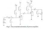
At present, I am designing a RF power amplifier. I have found a paper in IEEE entitled "Design of 2.1GHz RF CMOS Power Amplifier for 3G"(attached). Here is its schematic:
94893d1376537393-rf-pa.jpg

I am confused about how to model MOS transistor to calculate impdedance matching. To what extend I need to model parasitic parameters?
Thanks.
 

Attachments

  • RF PA.JPG
    RF PA.JPG
    21.7 KB · Views: 158
  • 04908575.pdf
    457.6 KB · Views: 96

At 2.1GHz you need to model parasitics fairly accurately. For example 1pF has an impedance of 75.8Ω at 2.1GHz.
 

Hi, and thanks for the help.
Can you tell me how can we know the value above?
For example, now if the operating is 1.5GHz, then how can I know the parasitic resistance and Cgs?
If possible, please give me some references about this?
 

Status
Not open for further replies.

Similar threads

Part and Inventory Search

Welcome to EDABoard.com

Sponsor

Back
Top