David Gold
Newbie level 4
Problem with electret mic & INA217 - attenuation instead of gain
Hello everyone,
I'm having problems with the combination of the two.
My goal is to record audio speech at low frequencies ( up to about 4kHz ).
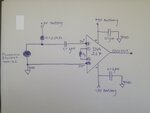
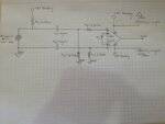
I'm using the schematics below to connect my electret mic to a Texas Instruments INA217 Instrumentation amplifier:

The gain equation for this amplifier is : GAIN = 1 + 10,000/Rg, where Rg is the value of the resistor between pins 1 & 8.
I tried to use all sorts of values for the gain. Theoretical gains of 50,100,200 all gave me a smaller peak to peak voltage while recording( attenuation! ).
I didn't have these problems when I connected the mic with a simple operational amplifier like the Texas Instruments TL071. With the
TL071 I recieved very large gains at the output and it was very clean and good.
I have 2 questions:
1)What do you think is the problem with this circuit?
2)In general, are the bypass capacitor values O.K for frequencies as low as 4kHz? Should I use larger capacitance capacitors?
Hello everyone,
I'm having problems with the combination of the two.
My goal is to record audio speech at low frequencies ( up to about 4kHz ).
I'm using the schematics below to connect my electret mic to a Texas Instruments INA217 Instrumentation amplifier:

The gain equation for this amplifier is : GAIN = 1 + 10,000/Rg, where Rg is the value of the resistor between pins 1 & 8.
I tried to use all sorts of values for the gain. Theoretical gains of 50,100,200 all gave me a smaller peak to peak voltage while recording( attenuation! ).
I didn't have these problems when I connected the mic with a simple operational amplifier like the Texas Instruments TL071. With the
TL071 I recieved very large gains at the output and it was very clean and good.
I have 2 questions:
1)What do you think is the problem with this circuit?
2)In general, are the bypass capacitor values O.K for frequencies as low as 4kHz? Should I use larger capacitance capacitors?
Last edited:
