Continue to Site

Welcome to EDAboard.com

Welcome to our site! EDAboard.com is an international Electronics Discussion Forum focused on EDA software, circuits, schematics, books, theory, papers, asic, pld, 8051, DSP, Network, RF, Analog Design, PCB, Service Manuals... and a whole lot more! To participate you need to register. Registration is free. Click here to register now.

Variable output voltage using a Boost Converter and SMPS

Status
Not open for further replies.

shatruddha

Full Member level 2
Joined
Nov 24, 2009
Messages
141
Helped
19
Reputation
38
Reaction score
19
Trophy points
1,298
Location
india
Activity points
2,177
HI All
I'm having a 600W 12V SMPS. I was wondering if its possible to have a variable output voltage using the same SMPS. Say I have my minimum output voltage requirement is 12V and it should Vary till 24V.
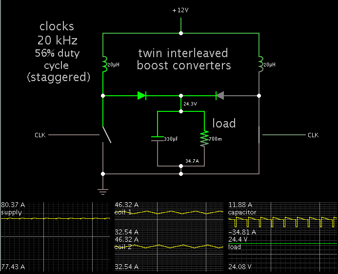
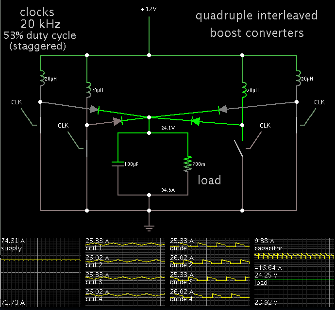
I thought of Cascading a Boost Converter to the output of the SMPS. The Specs that I decided are as follows
Vout Range - 12v to 24v
Iout Range - 20-40A
Frequency - 50kHz
Duty Cycle - 0 to 0.5
So it comes out that an Inductor of say 20-25 uH should work for me.
Now I need to finalize the components and Design an Inductor for the same.
Major Issue that I see is designing an Inductor. Are there any Inductors which are off the shelf or I can take out from any old SMPS. or any other easier and cheap way to procure the component.
Apart from it if there is anything that I'm missing please help me come over it.
 

To obtain 24V at 40A, your converter will need to have over 80 A coming from the 12V supply. The coil will need to handle similar peaks. You'll need to pay careful attention to reducing resistance everywhere you can.

For the power levels you're talking about, you may be better off using multiple interleaved boost converters, or a flyback, or an H-bridge.
 

I have a PC SMPS VP650P (Antec). It can deliver upto 70A at 12V, and thats sufficient for me. So may be I can limit my current output at 24V to be 35A. As you suggest, I as well was thinking on using two parallel boost converters. One of them active at a time. I found this really cool guy and his awesome posts.
http://danyk.cz/reg60v_en.html
I will try to recreate something like this. Except that I'm using an already proved model for getting my power supply.
 

For the sake of curiosity, here is a simulation to illustrate how twin interleaved boost converters might operate.

Overall resistance cannot be more than a few hundredths of an ohm.


I'm not saying this is the optimum design. When you start thinking of using more than one coil, you might as well also consider a transformer-based converter (flyback, forward, etc.).

The Danyk.cz link looks as though he does excellent work.

Sometimes there is an adjustment on computer power supplies, which might allow you to get higher volt levels. I do not know whether you could get 24V from your Antec supply, however.
 

WOw that looks beautiful. What software do you use for that?
I dont have a very in depth experience with power electronics, but for all I know about SMPS, it uses a feedback network to regulate the output voltage. So what I was thinking is, if I replace feedback resistor network with a potentiometer, I can vary the feedback value, and since SMPS always tries to adjust it to the Vref, I might be able to generate the desired output.
But I strongly doubt if this will work, since this feedback is before the transformer I guess and these high frequency transformers are very much specific to their input voltage.
Let me know if I'm missing something or I'm wrong somewhere.
 

WOw that looks beautiful. What software do you use for that?

This is Falstad's interactive animated simulator. A free download at:

www.falstad.com/circuit

The link below will open the simulator at his website, load my schematic above, and run it on your computer.

https://tinyurl.com/l75kx5e

You can experiment with values by right-clicking a component, and select Edit.

I dont have a very in depth experience with power electronics, but for all I know about SMPS, it uses a feedback network to regulate the output voltage. So what I was thinking is, if I replace feedback resistor network with a potentiometer, I can vary the feedback value, and since SMPS always tries to adjust it to the Vref, I might be able to generate the desired output.
But I strongly doubt if this will work, since this feedback is before the transformer I guess and these high frequency transformers are very much specific to their input voltage.
Let me know if I'm missing something or I'm wrong somewhere.

An optocoupler is typically used to convey the feedback level from an isolated secondary side back to the primary.

To regulate volt output of a boost converter, you'll need more complex circuitry than you see in linear regulators.
 

Hey Brad
Thanks a lot
now only problem left for me is, getting those Inductors. I'm sure it will be difficult to get these high current rating inductors off the shelf. I will try winding some core. If you have any suggestions here as well, I'd be obliged.
 

Here is an Edaboard thread about how to calculate turns, wiring, cores, etc.

https://www.edaboard.com/threads/229615/

You can arrange more than two boost converters in parallel. It allows you to use inductors with lower ratings.

To illustrate, a quadruple interleaved boost converter:

 
I had a few old SMPS around me. So I was thinking to take out its power transformer and rewind it to serve my purpose. How does that sound??
 

I have a PC SMPS VP650P (Antec). It can deliver upto 70A at 12V, and thats sufficient for me. So may be I can limit my current output at 24V to be 35A. As you suggest, I as well was thinking on using two parallel boost converters. One of them active at a time. I found this really cool guy and his awesome posts.
http://danyk.cz/reg60v_en.html
I will try to recreate something like this. Except that I'm using an already proved model for getting my power supply.

A simple method may be to redesign the existing transformer, and the feedback loop.
regards
padmanabhan
 

Well you may be right, but you are missing the whole point here. If I redesign the existing transformer, that means I will have to check the the complete loop and components that are used there. Its will be kind of redesigning the complete smps unit.
Moreover I want this unit to be portable enough, So I want an add on board, which I can connect to any existing power supply.
 

Hey Brad
thanx a lot
I found an old smps and used its core to wind my inductor. I don't have a LCR meter, but I used my DSO quad and I think that's approximately good enough reading.
Now next task that awaits is selection of components. I took out a few mosfets from old UPS and capacitors as well.
I could not find currect diodes though for such high current.
Apart from that, I used some normal 1n4007 diodes, but i think they wont work, since I checked drain voltage of mosfet and voltage after diode. After diode I do not see any voltage rise, whereas at drain I see some voltage pulses.
Another issue I found was, my inductor making noise at 20kHz, I thought that might be possible because of core saturation, so I changed the frequency to 50kHz at I do not hear any sound. Did I guess it right? or it was some other issue I'm still not sure of.
 

Status
Not open for further replies.

Similar threads

Part and Inventory Search

Welcome to EDABoard.com

Sponsor

Back
Top