Continue to Site

Welcome to EDAboard.com

Welcome to our site! EDAboard.com is an international Electronics Discussion Forum focused on EDA software, circuits, schematics, books, theory, papers, asic, pld, 8051, DSP, Network, RF, Analog Design, PCB, Service Manuals... and a whole lot more! To participate you need to register. Registration is free. Click here to register now.

[SOLVED] Optimal PCB Antenna Orientation?

Status
Not open for further replies.

Darkcobra

Member level 3
Joined
Nov 20, 2010
Messages
55
Helped
13
Reputation
28
Reaction score
14
Trophy points
1,288
Activity points
1,883
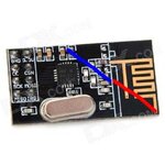
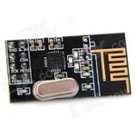
I have two RF modules (2.4Ghz, NRF24L01+ based, pictures follow). One uses a rubber duck antenna, which will be oriented vertically as shown.

The other uses a PCB antenna. There is no ground plane on the opposite side of the PCB area containing the antenna. Is there an optimal orientation of this module for best communications between the two?
pcbant.jpgduckant.jpg
 

That's something you may want to check empirically! The polarization (E-field) is in the PCB plane, I guess diagonally oriented, targetting to the upper right and lower left direction.
 
With a diagonal E-field polarization considered alone (and not other factors, like surroundings), it sounds like there is no inherent advantage to either flat mounting, or on-edge with the antenna highest? (Correct me if I'm wrong, I know next to nothing about RF.)

I did try the empirical approach, but this module provides no received signal strength measurement, which made the results coarse and confusing.
 

Because meander type is a monopole, the polarization is almost the same as a standard vertical monopole antenna (or the duck antenna in your setup).
So, the best coupling between antennas (giving the best communications between modules) is to place both antennas in vertical position (keeping the module using the printed antenna in the position shown in the picture).
 
Because meander type is a monopole, the polarization is almost the same as a standard vertical monopole antenna (or the duck antenna in your setup).
The polarization will be also affected by the small groundplane. Effectively, monopole and groundplane act as a dipole in the present case. So you'll most likely end up with a diagonal polarization and main lobe direction. However, nothing's been said yet about about connected instrument chasssis, wires, other boards etc. They may be utilized to extend the ground plane or decoupled on purpose.
 
Thank you both. I'm going to consider it theoretically equivalent to a dipole, somewhat like this, although I'm sure the exact angle may differ:

dipole.jpg

With any on-edge orientation superior to flat. I won't be coupling it to larger ground planes (at least not intentionally). And will typically be mounting it in the highest feasible point in a non-metallic enclosure, via a short header and away from other boards.

Eventually I'll have two masters with the external antenna for spatial diversity, as well as mesh routing between multiple devices with the PCB antenna; both of which should help make this more forgiving to my general naivete when it comes to RF.

Marking this thread solved, but feel free to add anything else that may be of help.
 

Status
Not open for further replies.

Part and Inventory Search

Welcome to EDABoard.com

Sponsor

Back
Top