Continue to Site

Welcome to EDAboard.com

Welcome to our site! EDAboard.com is an international Electronics Discussion Forum focused on EDA software, circuits, schematics, books, theory, papers, asic, pld, 8051, DSP, Network, RF, Analog Design, PCB, Service Manuals... and a whole lot more! To participate you need to register. Registration is free. Click here to register now.

Ads simulation types

Status
Not open for further replies.

aashishsharma

Member level 5
Joined
Jun 26, 2013
Messages
93
Helped
4
Reputation
8
Reaction score
4
Trophy points
8
Activity points
683
hey
After working a long time on ads. I just got all confused.
Please can anyone clarify different type of simulation modes in ads
in ac simulation one can get voltage vs time plot as well in HB simulation too we can have that.
basically in need to know different type of simulation used in ads and when to use when
Thanks in advance
 

Hello,

You may use AC or s-parameter simulations for linear circuits, or nonlinear circuits (i.e. those containing transistors, diodes etc.) under a small-signal assumption. Even if you feed the circuit with tens of volts, the simulator will linearise your components at the selected operating point and give you an input/output relationship as if all components were linear.

Transient simulation and Harmonic Balance simulation do take into account the nonlinearity of your components, assuming you have provided the simulator with nonlinear models. They operate differently though, and while you can observe the time varying response of your circuits under transient simulation, you can only get the steady-state output with a Harmonic Balance simulation. Additionaly, transient simulation can handle stronger nonlinearities than the Harmonic Balance. On the other hand, it also takes much longer depending on the time constants in your circuits.

ADS has several other simulations like Large signal s-parameter simulation, circuit envelope simulation etc. but these are just derivatives of the ones above. Do ask if you need further clarification.
 

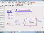
hey I tried different simulation types with simple circuit to visualise how exactly they are working. I used RC filter (image attached).
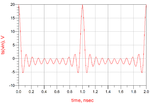
first i used HB simlulation,made frequency sweep and chose rectangular plot. I added vin in plot traces and attribute dialogue box and chose time domain signal and plotted and it worked fine. However when I used ac analysis single frequency plot wrt time was good but as soon as swept frequency vin vs time plot appeared as shown in image attached.
I was hoping to get same reult as in HB simulation ie single curve for 1 plot.
Any ideas why this is happening. Is it because its not 1 curve each for 1 frequency just frequency changes in single curve?? Even if that is the explanation vin ampliude is varying ???
thanks in advance.

- - - Updated - - -

send2.pngsend1.png
 

Hello aashishsharma, here's an attempt to answer your questions. I may also raise some questions on the method you chose.

- I assume you wish to see that HB and AC simulations treat a linear circuit in exactly the same way. In fact, what is happening inside the HB simulator in the case of a completely linear circuit is just AC analysis, so you should indeed get the same results.

- During HB simulation, do you use the "RF_freq" variable to perform a frequency sweep? Do you do this inside the "Sweep" tab of the HB simulator? Shouldn't you set the input source frequency to vary with the "RF_freq" variable to obtain a meaningful result?

- When performing a frequency sweep, it is better to compare the results over frequency, rather than time. The time domain signal you obtain during AC sweep is rather meaningless in the way you want to use it. To see this, change the step of the frequency sweep to 100 MHz, 2 GHz etc. and see what happens. It is just an inverse Fourier Transform of the flat "Vin" vs. "freq" response, and the inverse FT of a flat frequency response is an impulse, right? However, the position of the impulse in time will change depending on where you set the step frequency (it will be 1/Fstep).

- Instead, compare "Vout" vs. "freq" (of the fundamental tone, in HB case) for each analysis. You will see that the results will match.
 

- yes i used rf_freq variable in sweep tab as well as freq tab to perform freq sweep in HB simulation . I think frequency tab will set freq as variable RF_feq and sweep tab will sweep the parameter. I also used RF_freq variable as input source frequency as i heard that one has to keeb HB simulation frequency and source frequency same. anyways i dont really understand difference between the two(ie freq given in source which is for sure frequency of signal ,source provides and HB simulation freq i am considering to be same as source freq correct me if i am wrong as in ac simulation frequency set in simulation tab is source freq we dont need to specify freq to our source).
also if i just keep the source freq as RF_freq ( defined variable) and in the sweep tab keep parameter to sweep RF-freq while frequency tab just 1ghz it gives a warning -"source 'SRC1',( 1* freq[1] = 4e+09 hz is 3e+09 hz away from the closest analysis frequency at 1e +09. The maximum allowed frequency difference is 1000hz this spectral component is turned off for this simulation." this warning is repeated for every frequency swept ie 1ghz to 10ghz in step of 1 ghz
-Also FT of flat freq response will be a sinc function not impulse( single freq pure sine wave will give an impulse at that particular freq in FT). So in my output since I am sweeping the ac analysis freq linearly vin vs freq will be a straight line at 0 db (kind of a pulse and) ie vin=1 at all freq and Inverse fft of this signal is being depicted in the time domain representation i posted i guess??
 

- yes i used rf_freq variable in sweep tab as well as freq tab to perform freq sweep in HB simulation . I think frequency tab will set freq as variable RF_feq and sweep tab will sweep the parameter.

Correct.

- I also used RF_freq variable as input source frequency as i heard that one has to keeb HB simulation frequency and source frequency same.

Good.

- anyways i dont really understand difference between the two(ie freq given in source which is for sure frequency of signal ,source provides and HB simulation freq i am considering to be same as source freq correct me if i am wrong as in ac simulation frequency set in simulation tab is source freq we dont need to specify freq to our source).

In AC simulation, I checked and verified this to be the case. But in HB, you may want to perform analyses at frequencies that are not the source frequency (as in intermodulation analysis) and therefore the two are uncoupled. Hence, they have to be manually set to be the same thing if you want them to be the same.

- also if i just keep the source freq as RF_freq ( defined variable) and in the sweep tab keep parameter to sweep RF-freq while frequency tab just 1ghz it gives a warning -"source 'SRC1',( 1* freq[1] = 4e+09 hz is 3e+09 hz away from the closest analysis frequency at 1e +09. The maximum allowed frequency difference is 1000hz this spectral component is turned off for this simulation." this warning is repeated for every frequency swept ie 1ghz to 10ghz in step of 1 ghz

As above. HB can do analysis close to one of the generated frequencies, but not far away. When you sweep the source between 1 - 10 GHz and keep the analysis frequency at 1 GHz, HB complains that the two frequencies are far apart.

- -Also FT of flat freq response will be a sinc function not impulse( single freq pure sine wave will give an impulse at that particular freq in FT). So in my output since I am sweeping the ac analysis freq linearly vin vs freq will be a straight line at 0 db (kind of a pulse and) ie vin=1 at all freq and Inverse fft of this signal is being depicted in the time domain representation i posted i guess??

Inverse FT of flat response (i.e. H(w)=1 for all w) is a Dirac Delta function. The reverse also holds. The sinc responses you obtain approach to an impulse train as you increase the resolution of the FFT analysis.

Going back to your original question, have you been able to understand the simulation types and their uses?
 
yes prog_doctor thanks for your help :)
will post any new query if it crop up
 

Status
Not open for further replies.

Part and Inventory Search

Welcome to EDABoard.com

Sponsor

Back
Top