Continue to Site

Welcome to EDAboard.com

Welcome to our site! EDAboard.com is an international Electronics Discussion Forum focused on EDA software, circuits, schematics, books, theory, papers, asic, pld, 8051, DSP, Network, RF, Analog Design, PCB, Service Manuals... and a whole lot more! To participate you need to register. Registration is free. Click here to register now.

help in mickroC for PIC to PIC communication using RF 434MHz modules

Status
Not open for further replies.

choura

Member level 1
Joined
Apr 28, 2010
Messages
41
Helped
3
Reputation
6
Reaction score
3
Trophy points
1,288
Location
algeria
Activity points
1,558
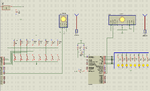
I'm using pic16f877a, crystal 4MHz with RF 434MHz but still doesn't working.
my program for Tx

void main()
{
TRISB = 0xFF;
PORTB = 0;
UART1_Init(9600); // Initialize UART module at 9600bps
Delay_ms(100); // Wait for UART module to stabilize
while (1)
{ // Endless loop
UART1_Write(PORTB); // and send data via UART
Delay_ms(500);
}
}


the second part of Rx is

void main()
{
TRISB = 0;
PORTB = 0;
UART1_Init(9600); // Initialize UART module at 9600bps
Delay_ms(100); // Wait for UART module to stabilize
while (1)
{ // Endless loop
if (UART1_Data_Ready())
{ // If data is received,
PORTB = UART1_Read(); // read the received data,
}
}
}

please help brothers
 

Attachments

  • my project n (4).JPG
    my project n (4).JPG
    71.5 KB · Views: 88

You have not pressed any buttons and hence PORTB of Transmitter is 0x00 and so PORTB of Rx is also 0x00. Zip and attach the proteus file and mikroC Code.
 

here the Proteus and hexes files in rar
 

Attachments

  • hexes files.rar
    38.5 KB · Views: 61

sir can i use the RF434MHz because this what I have
 

thank you brother , I never forget your help for me

thank you
 

there is error when i uploaded the hex files to both microcontrollers
i have just uploaded the video for the project

- - - Updated - - -

the Rf speed is 4600bps
is this working correctly with the program
 

Attachments

  • Vidéo0004.rar
    954.3 KB · Views: 78

If you used my code then you should not get the flickering of LED. See if Watch dog timer is resetting. Disable watchdog timer and it will work fine.

Try this version.
 

Attachments

  • RF 433 MHz v1.rar
    142.9 KB · Views: 69
Last edited:

it still doesn't work when I removed the reset ( you mean here to remove R1 and R2 from +5v);
 

what is the wrong with power supply ?

i'm using the capacitor which used in the circuit you have seen
 

Filtering is needed otherwise there will be ripples in DC output. If you are using battery instead of transformer then there is no need of Capacitor.
 

i'm using battery of ultra power ACE with 9v

it can handle the circuit

i'm sorry for taking your time
 

Connect a led to pin RC0 and in the code just make pin RC0 high all the time. Do it for both the uCs. If led on RC0 blinks then watchdog timer is resetting.
 

it still lighting but very weak, what does mean that
 

I was mistake with led, I'm sorry for that, when I confirmed again the led always 0.
 

Status
Not open for further replies.

Part and Inventory Search

Welcome to EDABoard.com

Sponsor

Back
Top